The line voltage enters the switch outlet box and the hot wire will connect to every switch. Turn the power back on.

Wiring Diagram For Ceiling Light H1 Wiring Diagram
Ceiling light wiring diagram. For ceiling light wiring diagrams with a single switch start here. Remember that the hot black or red wire goes to the brass colored screw neutral white to the silver screw. The neutrals are connected together using a terminal connector. Instead of taking the feed wire from the consumer unit to the ceiling rose it is taken to the switch. Take a closer look at a ceiling fan wiring diagram. Wire the new fixture in the box and mount it to the ceiling.
The permanent live wire is wired into the switch and the switched live into the switched live terminal. If there is a bare ground wire in the fixture often found in ceiling fans and exterior fixtures twist it. Patch the wall where the temporary hole was cut. Wiring a light switch. If the cable colours in you ceiling rose are brown blue and greenyellow you probably want to start here. With these diagrams below it will take the guess work out.
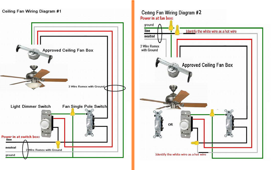
For ceiling light wiring diagrams with a single switch start here. It reveals the parts of the circuit as simplified shapes as well as the power and also signal links in between the gadgets. A wiring diagram is a simplified standard photographic representation of an electrical circuit. This wiring diagram illustrates the connections for a ceiling fan and light with two switches a speed controller for the fan and a dimmer for the lights. Ceiling fan and light switch wiring diagram. The grounding conductor is not shown in order to simplify the wiring diagram.
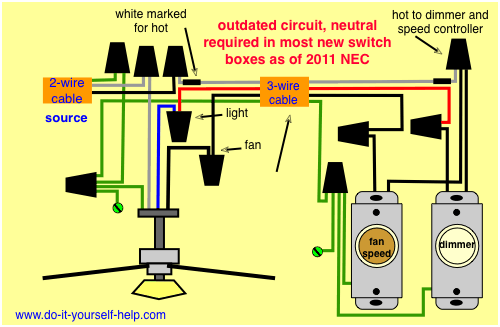
For ceiling light wiring diagrams with a two way switching start here. This might seem intimidating but it does not have to be. Pick the diagram that is most like the scenario you are in and see if you can wire up your fan. Multiple light wiring diagram this diagram illustrates wiring for one switch to control 2 or more lights. The hot and neutral terminals on each fixture are spliced with a pigtail to the circuit wires which then continue on to the next light. The source is at sw1 and 2 wire cable runs from there to the fixtures.
Mount the electrical box in the ceiling with more madison bars and screws. Switch hots and line neutral will connect to a 3 wire cable that travels to the fanlight outlet box in the ceiling. Interior ceiling lights usually have no ground wire connection unless there is a receptacle in addition to the socket. From the ceiling a three conductor cable with a grounding conductor is used to send power to a light switch. Scott installed the boxie ceiling mounted led fixture manufactured by tech lighting. This is an alternative way of wiring a lighting circuit.
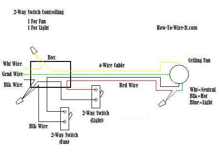
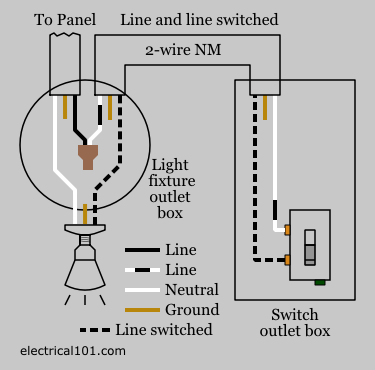
The photo above depicts the wiring diagram of a ceiling light and light switch with the power from the circuit breaker panel entering the ceiling electrical box. Collection of ceiling fan and light wiring diagram. From the switches 3 wire cable runs to the ceiling outlet box. The source is at the switches and the input of each is spliced to the black source wire with a wire nut.
Gallery of Ceiling Light Wiring Diagram