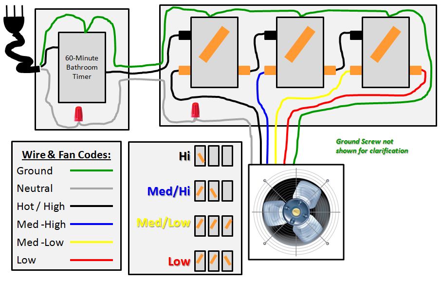
When wiring this switch you can choose if youd like to illuminate it because of the independent lamp attached to terminals 8 and 7. Variety of 4 position selector switch wiring diagram.

Relays And Switches
4 position switch wiring diagram. Variety of 4 position rotary switch wiring diagram. 4 position selector switch wiring diagram collection wiring diagram for honeywell thermostat th6220d1002 position. A four switch configuration will have two 3 way switches one on each end and two 4 way switches in the middle. This is the wiring for a dimmer in a 4 way circuit. Microsoft word ignition switch wiring diagram author. Circuit breaker wiring diagram brilliant 3 position selector.
Three wire cable runs between the switches and the outlet. A wiring diagram is a streamlined conventional pictorial representation of an electric circuit. A wiring diagram is a streamlined traditional pictorial representation of an electrical circuit. It reveals the parts of the circuit as simplified forms and also the power and also signal connections between the tools. A 4 way switch wiring diagram is the clearest and easiest way to wire that pesky 4 way switch. To make this circuit work a 3 way dimmer can be used in place of one or both of the standard 3 way switches.
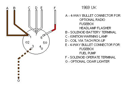
It reveals the elements of the circuit as simplified shapes and the power and signal connections between the tools. In the diagrams below the first switch 3 way common terminal connects to line voltage. Switch brass terminals on switch wiring diagram for 4 position universal ignition switch product code p00940. In this diagram two 3 way switches control a wall receptacle outlet that may be used to control a lamp from two entrances to a room. In fact a dimmer can be used this way in place of any of the 3. I have a few of the most common ways in wiring a 4 way switch to help you with your basic home wiring projects.
Or these terminals can be ignored for non backlit switch banks. Three wire cable runs between all the switches and 2 wire cable runs to the light. A wiring diagram normally offers details regarding the loved one position as well as plan of tools as well as terminals on the gadgets to aid in building or servicing the tool. This circuit is wired the same way as the 3 way lights at this link. Conventional 4 way switch wiring. The source is at the sw1 where the hot is connected to.
The first switch 3 way travelers brass color connect to one pair of the second switch 4 way travelers black or brass color. 4 way switches have four terminals each with two pairs of travelers one set usually black and one set usually brass color. Rotary switch wiring diagram guitar refrence how to wire a 3 way. 3 way switched outlet wiring. The wiring diagram to the right will show how to wire and power this 12v 20amp on off on 3 way carling contura rocker switch. It reveals the elements of the circuit as streamlined forms as well as the power and signal links between the gadgets.
A wiring diagram is a streamlined standard pictorial depiction of an electrical circuit. Collection of 4 wire ceiling fan switch wiring diagram. 4 way dimmer switch wiring diagram.
Gallery of 4 Position Switch Wiring Diagram