Wiring a single phase 220 volt motor is straightforward. For example if there are three 15 amp motors in the circuit the ampacity rating of the wire feeding the circuit must exceed 15 15 15 125 4875 amps.

3 Phase Motor Wiring Diagrams Century H1 Wiring Diagram
3 phase ac motor wiring. This is because the motors single phase actually operates on the difference between the two 120 volt phases that comprise the residential 240 volt input. In the alternator three stator windings or say three independent coils typically separated by some number of degree of rotation and hence the current produced by that coils is also separated by some degrees of rotation which is typically 120 degrees. The voltage cycle of each line lags its predecessor by 120 degrees l2 reaches its peak voltage after l1 and l3 reaches its peak voltage after l2. Single phase 220 volt ac motors are really two phase 240 volt motors especially when compared to three phase 208 volt motors and single phase 120 volt motors. Three phase ac power is generated by a three phase alternator also called as ac generators in the power plants. Although the national electric code does not specify specific conductor colors for three phase current it is common to use black red and blue wires to identify lines l1 l2 and l3 respectively.
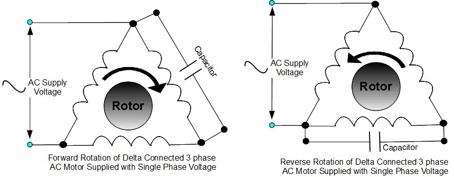
Capacitor motor single phase wiring diagrams always use wiring diagram supplied on motor nameplate. When a motors power supply is brought in from three wires instead of just one with the power delivery cycling through each of these in sequence hence the a part of ac it permits an effective power level that is 3 times higher about 1728 times higher than a corresponding single phase set up would be. Multi speed 3 phase motor 3 speeds 1 direction power control diagrams one line diagram of simple contactor circuit. Different regions may use different voltages. If you need to have the rotation correct the first time then simply get a phase rotation meter that can be used to see what the rotation is before you connect to the equipment. A three phase motor is more efficient than a single phase motor because of the peculiarities of alternating current ac.
Three phase electrical wiring installation in home iec nec. This video explains how to wire a three phase induction motor to an external electricity source. Although these systems may seem intimidating at first a walkthrough on 3 phase wiring for dummies will help clarify the whole situation. Three phase motors are more efficient than single phase motors and are commonly found in applications requiring more than 75 horsepower. They can also be found in large residential complexes and appliances requiring a large amount of power. Three phase systems are extremely common in industrial and commercial settings.
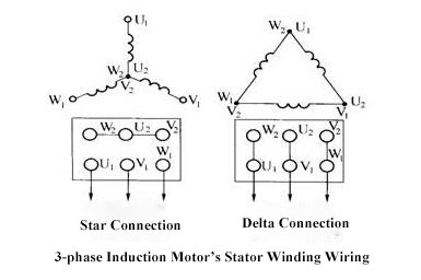
Be very careful when working with 3. This three phase power from the alternators is further transmitted to the distribution end through transmission lines. For circuits with multiple motors the ampacity rating of the wire must be at least 125 of the full load current of the largest motor plus the sum of full load currents for the rest of the motors. 3 phase electric motor wiring and motor rotation when connecting any motor to 3 phase power you could find that the rotation is wrong and if it is all you have to do is shut off the power and swap any two lines of the 3 phase power and this will change the rotation. It also shows the difference between delta and star connections used to connect the motor coils.
Gallery of 3 Phase Ac Motor Wiring


.png)