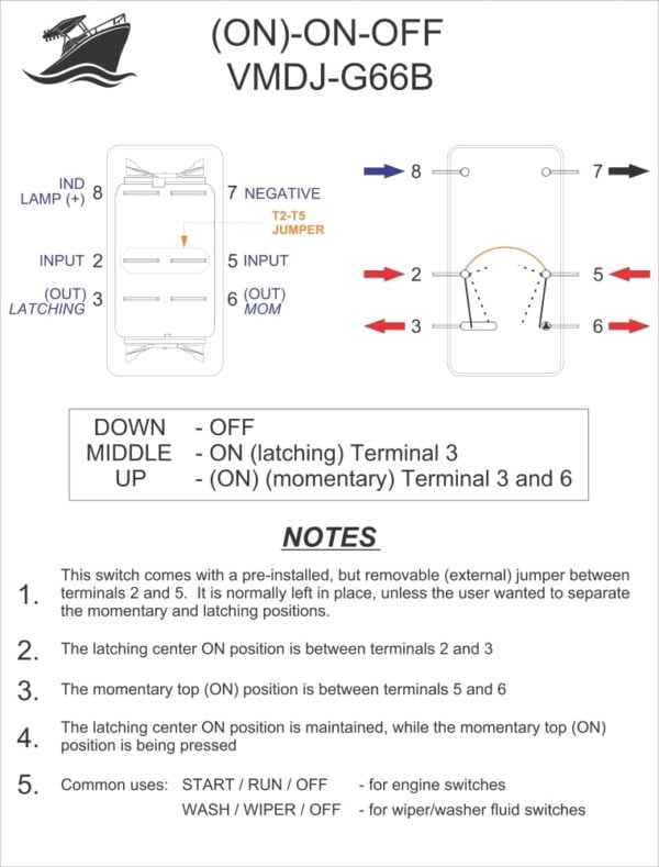
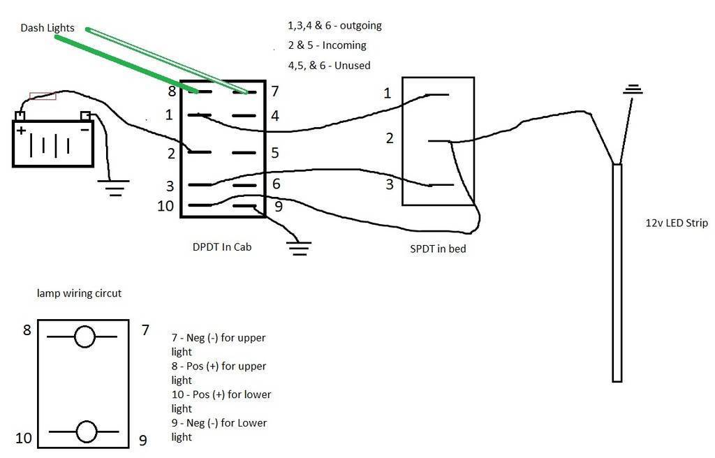
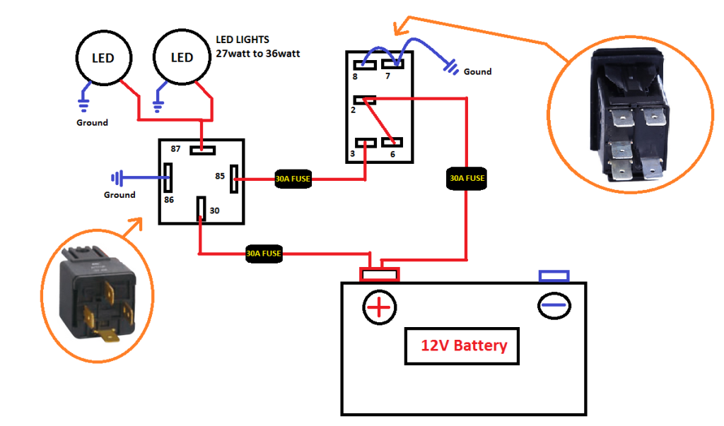
Terminal 2 is connected to power. Terminals 3 can flip between terminals 1 and 5.

Automotive Toggle Switch Wiring Diagram Yamahamonster
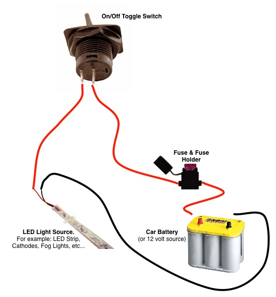
Automotive toggle switch wiring diagram. Applies to spot switches non led switches basic 2 wire switches 2 prong. Generally used in 12volt installs for on off switches. We have over 5000 products i. Photo of wiring diagram 12 volt the digital imagery with the identify wiring diagram momentary toggle transfer high quality for above is tagged with. A wiring diagram is a streamlined standard photographic representation of an electrical circuit. How to wire a on off on toggle switch diagram.
How to wire up an on off toggle switch. Below is the schematic diagram of the wiring for connecting a dpdt toggle switch. Quentacy 19mm 3 4 metal latching pushbutton switch 12v buy quentacy 19mm 3 4 metal latching pushbutton switch 12v power symbol led 1no1nc spdt on off black waterproof toggle switch with wire socket plug blue how to wire a 3 way switch wiring diagram how to wire 3 way light switches with wiring diagrams for different methods of installing the wire between boxes detailed instructions and wiring diagrams. Terminal 1 is connected to one load or accessory terminal 3 is connected to another load or accessory. We will now go over the wiring diagram of a dpdt toggle switch. How to wire a toggle switch on off switch basic.
A dpdt toggle switch has 6 terminals. Automotive wiring diagram. Here is a diagram of a spdt toggle switch. Assortment of on off on toggle switch wiring diagram. This switch body does have two isolated negative inputs t9 and t7 for each lamp or led in the switch. Three pin toggle switch wiring diagram 4 way toggle switch wiring diagram car toggle transfer wiring diagram carling toggle transfer wiring diagram dpdt toggle switch ac wiring diagram ford f250 toggle transfer wiring diagram illuminated toggle transfer wiring diagram industrial toggle transfer wiring.
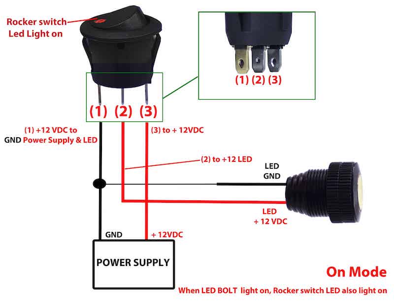
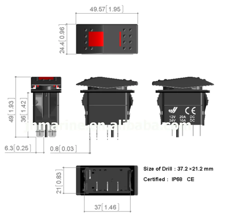
It reveals the components of the circuit as simplified forms and also the power as well as signal links in between the devices. The switch is always making one of the two connections and flips between them. So if a fan is connected to terminal 1 and a motor is connected to terminal 5 terminal 3. These terminals receive the power necessary to drive the loads on terminals 1 and 5 and 2 and 6. Notice on the wiring diagram that of the 10 prongs spade connectors called termianls on the back four 4 make the rocker switch lights function while the remaining six are used for the electromechanical switching contacts. It shows the components of the circuit as simplified shapes and the talent and signal contacts surrounded by the devices.
Terminals 3 and 4 represent the toggle switch. 3 position toggle switch wiring diagram wiring diagram is a simplified satisfactory pictorial representation of an electrical circuit.
Gallery of Automotive Toggle Switch Wiring Diagram