Anyone have vs wiring diagrams. As a verb diagram is to represent or indicate something using a diagram.

Electronics Drafting Wiring Diagrams
Wiring diagram vs schematic. A wiring diagram is a type of schematic which utilizes abstract photographic symbols to reveal all the interconnections of parts in a system. Dustyvs your resident mechanic. What different between ladder diagram schematic diagram and wiring diagram read more. Amit 135 lesson 7 ball mills circuitsmining mill. Diagram is a synonym of schematic. You may have heard them very often but they vary each other slightly.
Wiring diagrams vs line diagrams most of the diagrams in this book are shown in two ways. What is the difference between a schematic a wiring diagram. 1964 ford truck f 100. Wiring representations mainly shows the physical setting of parts and connections in the. Schematic diagram for samsung mx c730 mx c630 power amp read more. As nouns the difference between schematic and diagram is that schematic is a drawing or sketch showing how a system works at an abstract level while diagram is a plan drawing sketch or outline to show how something works or show the relationships between the parts of a whole.
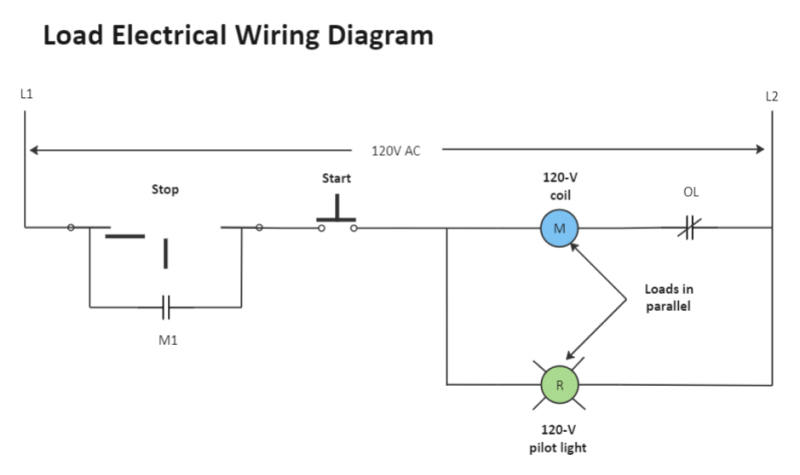
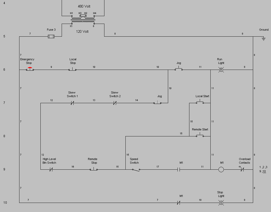
There is a wiring diagram and adjacent to it a line diagram line diagrams are included because their use is becoming more widespread and we believe it is advantageous to learn to use them. 12 volt conversion ford 9n 2n wiring diagram read more. Wiring diagrams mainly shows the physical position of components and connections in the built circuit but not necessarily in logic order. Wiring diagram vs schematic wiring diagram is a simplified okay pictorial representation of an electrical circuit. Symbols that represent the components in the circuit and lines that stand for the links in between them. Its most useful for learning the overall operation of a.
Start date nov 20 2010. It reduces integrated circuits into sub components to make the systems functional logic easier to understand. Schematic is a synonym of diagram. Active high pass filter circuit diagram read more. Its very easy to obtain confused about wiring representations and also schematics. 1966 chevrolet el camino wiring diagram part 2 read more.
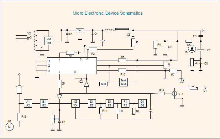
The factor cf is the correction for non standard conditions including wet open circuit wet closed circuit wet and dry grinding over size feed and. 2003 2004 kawasaki zx6r 636 wiring diagram read more. Joined jan 22 2010 messages 57 reaction score 1 points 0 location. Schematics circuit diagrams wiring diagrams electrical diagrams are commonly used in engineering diagrams. Schematics emphasize on how circuits work logically. It shows the components of the circuit as simplified shapes and the faculty and signal friends amongst the devices.
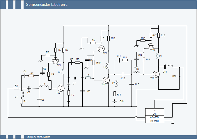
Every electrical component such as a resistor capacitor and inductor has a standard symbol. As a adjective schematic is represented simply. Schematics are symbolic representations of complete circuits or systems created during the design phase. It emphasizes on the layout of the wires. Schematics its easy to get confused about wiring diagrams and schematics. Several bonded and unbonded metal and semiconductor strain gages read more.
This article illustrates the differences between schematic diagrams and circuit diagrams and it may benefit you a lot in identifying the components of an electric system tracing a circuit and even fixing electrical. Nov 20 2010 1 d. Wiring diagrams are made up of 2 things. Refer to this page to learn the differences between schematic diagrams and circuit diagrams.
Gallery of Wiring Diagram Vs Schematic