Ceiling fan switch wiring diagrams 1. Black speed switch three wire capacitor.
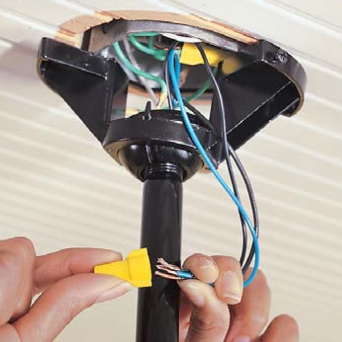
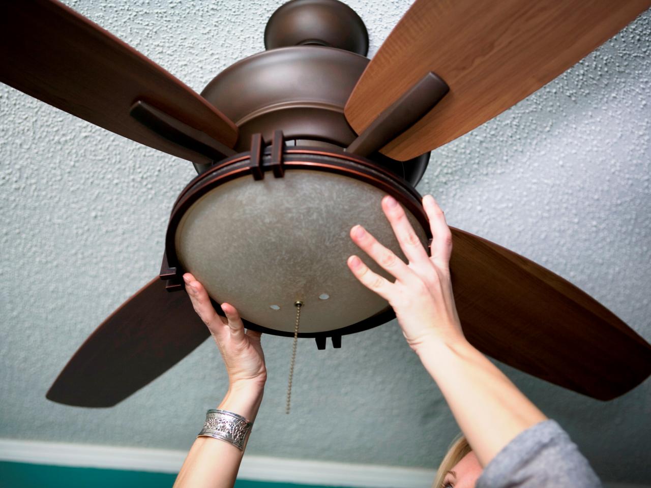
How To Install Ceiling Fans Family Handyman
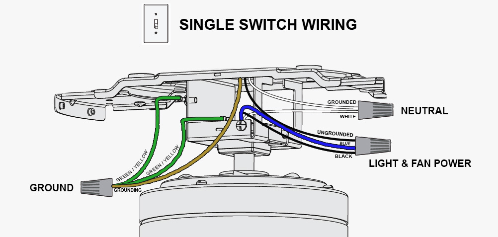
Typical ceiling fan wiring. Still looking for help. To be noted that the wiring diagram is for ac 220v single phase line with single phase ceiling fan motor. Ceiling fan wiring diagram australia best replacing a ceiling fan. Take a closer look at a ceiling fan wiring diagram. June 1 2019 by larry a. 1 to l c1 1 and c1 2.
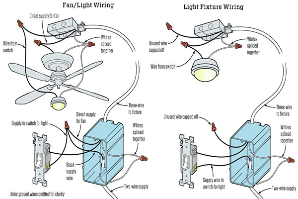
The speed is varied by changing the capacitance in series with one of the coils. 2 to 1 2 med. Pick the diagram that is most like the scenario you are in and see if you can wire up your fan. A typical ceiling fan motor contains two coils. Switching the light. Wiring a ceiling fan and light 1.
Hampton bay ceiling fan wiring schematic. This might seem intimidating but it does not have to be. Ceiling fan wiring diagram 2. Wiring a ceiling fan and light getting started. Turn off power at the breaker. Before you can start wiring your new ceiling fan youll need to turn off the.
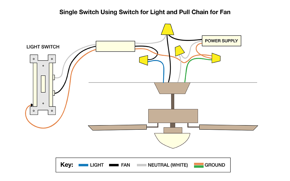
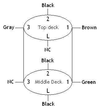
Ground connection diagram is shown separately. Speed switch connection table. Variety of hampton bay ceiling fan wiring schematic. It reveals the components of the circuit as simplified forms and also the power. In this diagram the black wire of the ceiling fan is for the fan and the blue wire is for the light kit. With these diagrams below it will take the guess work out.
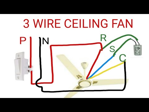
Hampton bay fan wiring schematic sample. This is a simple illustrated circuit diagram of ceiling fan. 2 to 1 and 3 3 slow. Switching the light and using the pull chain for the fan single switch this method and the following are the most. 1 to l and c1 1 2 med. Free wiring diagram menu.
Ceiling fan wiring diagram 1. One or both coils may be connected to capacitors. The wires inside of a ceiling fan are relatively simple but you have to know what each one. Powered ceiling fan andor light without any switches no switches this method is often used when you simply cannot. Speed switch connection table. Need step by step instructions on replacing ceiling fan.
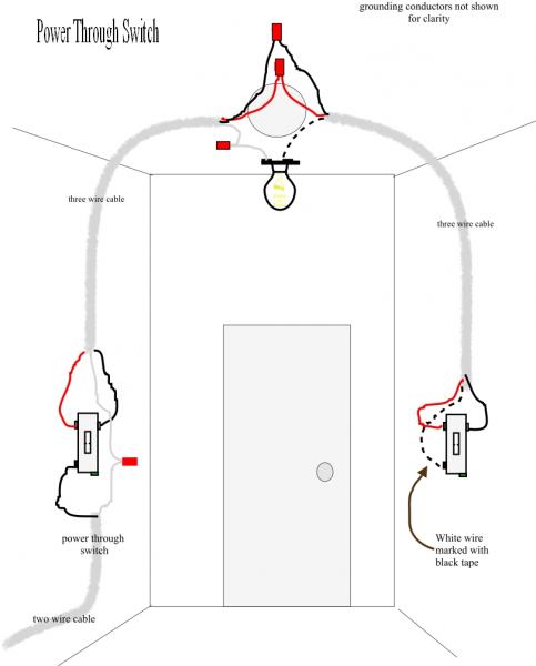
Black speed switch with only three terminals connected two wire capacitor. 1 to l and c1 2 3 slow. The fan control switch usually connects to the black wire and the light kit switch to the red wire of the 3 way cable. 2 to 3 do not use an electronic speed control on this type of fan. A wiring diagram is a simplified conventional photographic depiction of an electric circuit. No connection 1 fast.
Here a simple spst switch is used to supply power or not to the fan motor and a regulator is used to controlling the fan speed.
Gallery of Typical Ceiling Fan Wiring