Click on the image to enlarge and then save it to your computer. Assortment of single phase motor wiring diagram forward reverse.

Two Phase Motor Wiring Diagram Bmw Rpg4 Vovbernheze Nl
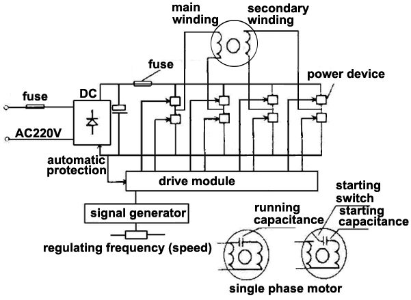
Two phase motor wiring diagram. Collection of baldor single phase motor wiring diagram. Auxiliary contacts 53 54 wiring diagrams 55 57 gi 20. Diagram dd5 two speed motors for all other single phase wiring diagrams refer to the manufacturers data on the motor. A simplified diagram of a two phase alternator two phase electrical power was an early 20th century polyphase alternating current electric power distribution system. Typical wiring diagrams diagrams are helpful in wiring up systems two speed manual motor starter is designed for starting protecting small single phase two speed ac fan motors 3 phase 2 phase 3 wire two speed starter bulletin 609ts sizes 0 1 3 phase 2 phase 3 wire for separate all. So if you desire to acquire all of these outstanding photos about stepper motor wiring diagram click on save link to store the images in your personal computer.
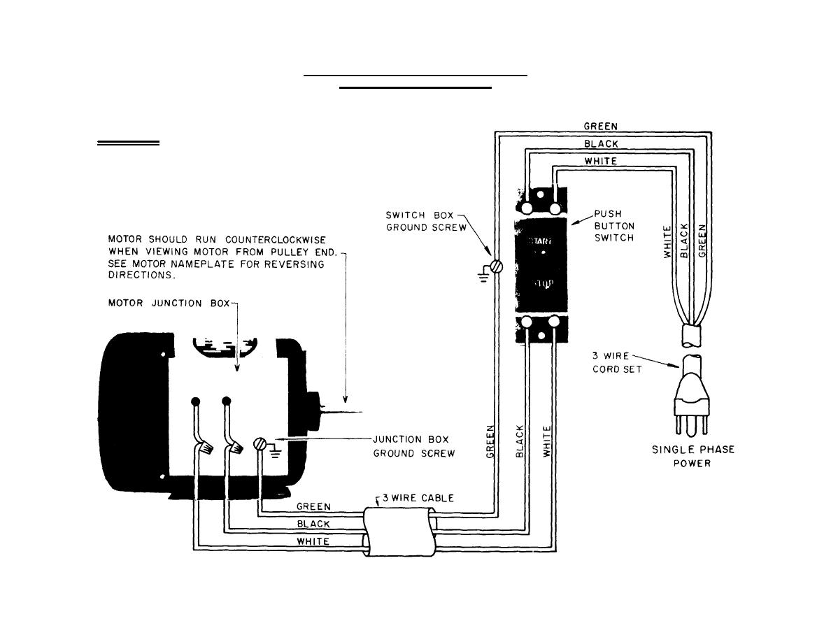
Single phase motor wiring diagram with capacitor baldor single phase motor wiring diagram with capacitor single phase fan motor wiring diagram with capacitor single phase motor connection diagram with capacitor every electrical arrangement is made up of various unique pieces. Single phase motor wiring diagram forward reverse single phase motor reverse and forward connection with capacitor wiring diagram. This magnetic field pulls. The motors starter wires directly to the motors wire terminals. It shows the components of the circuit as simplified shapes and the capacity and signal contacts between the devices. It is to be.
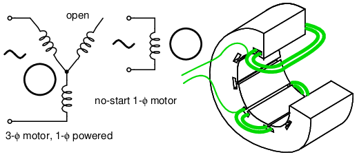
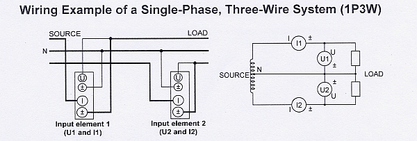
Two circuits were used with voltage phases differing by one quarter of a cycle 90. A three phase motors large size and high starting torque usually limit its use to industrial settings. When the motors switch is turned on voltage flows through the contactors coil creating a magnetic field. Thermal contacts tb white m 1 z2 yellow z1 blue u2 black u1 red bridge l1 and l2 if speed controller sc is not required m 1 ln e. This differs from a schematic representation. Each component ought to be placed and linked to different parts in particular manner.
A wiring diagram normally offers info regarding the family member setting and also arrangement of tools and terminals on the tools to assist in structure or servicing the device. Usually circuits used four wires two for each phase. If not the arrangement wont work as it should be. It is evident from the phasor diagram that the current through the starter winding is leads the voltage v by a small angle and the current through the main winding im lags the applied voltage. Two phase motor wiring diagram wiring diagram is a simplified customary pictorial representation of an electrical circuit. It is important to point out from the phasor diagram that the phase difference between im and is is almost 80 degrees as against 30 degrees in a split phase induction motor.
Thus a capacitor start induction run motor produces a better rotating magnetic field than the split phase motors. A wiring diagram is a streamlined traditional photographic depiction of an electrical circuit. Diagram dd6 diagram dd7 m 1 ln e diagram dd8 ln e l1 l2 l3 sc z1 u2 z2 u1 cap. Theyre available for download if youd prefer and want to own it just click save symbol on the web page and itll be instantly. Motor starters have a set of contactors. It shows the elements of the circuit as streamlined shapes as well as the power and signal links in between the tools.
Gallery of Two Phase Motor Wiring Diagram