Next the incoming white neutral wire is attached to the light fixture as usual and the black wire from the switch is connected to the light fixture. A white wire signifies a neutral wire.
Switch Diagrams
Switch loop wiring diagram. Flow switch wiring diagram sample. When the electrical source originates at a light fixture and is controlled from a remote location a switch loop is. Featuring wiring diagrams for single pole wall switches commonly used in the home. A first check out a circuit diagram may be confusing yet if you could check out a subway map you can review schematics. Wiring diagram for motor starter 3 phase controller failure relay electrical pleasing three and contactor. The source is at the outlet and a switch loop is added to a new switch.
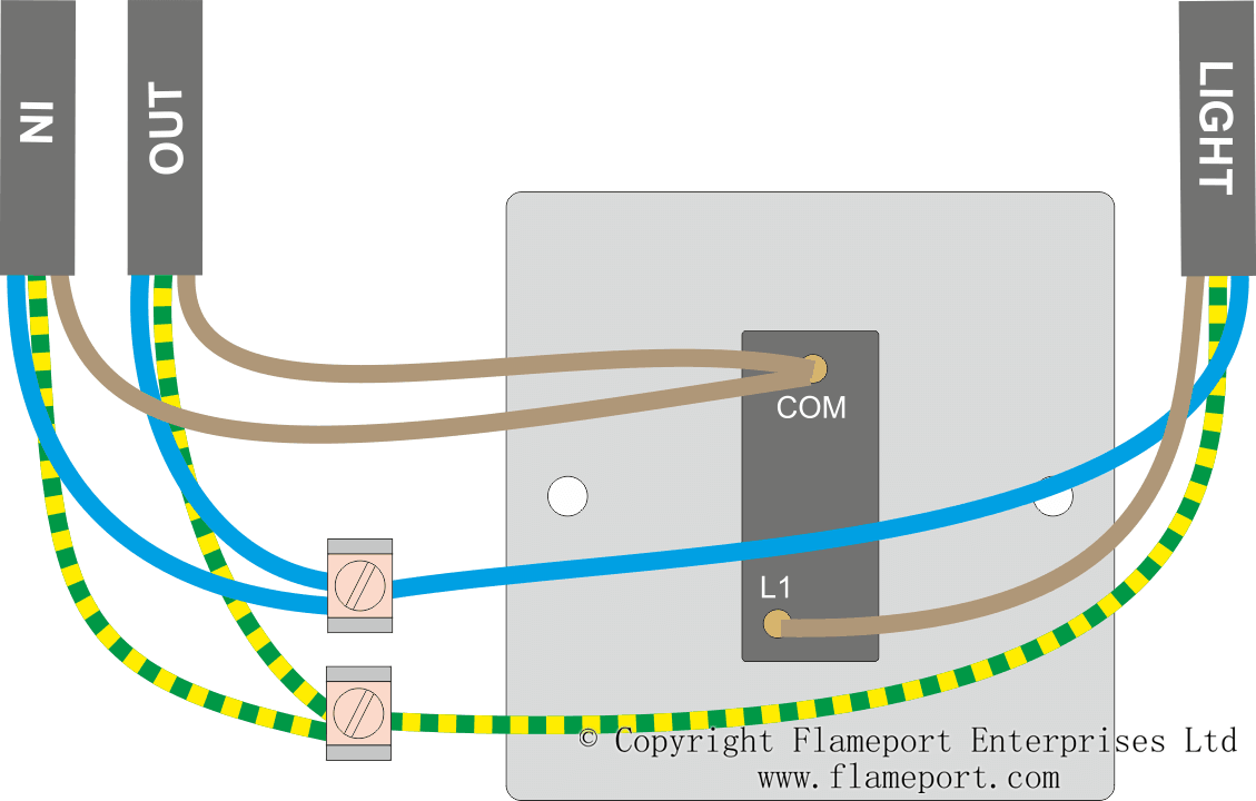
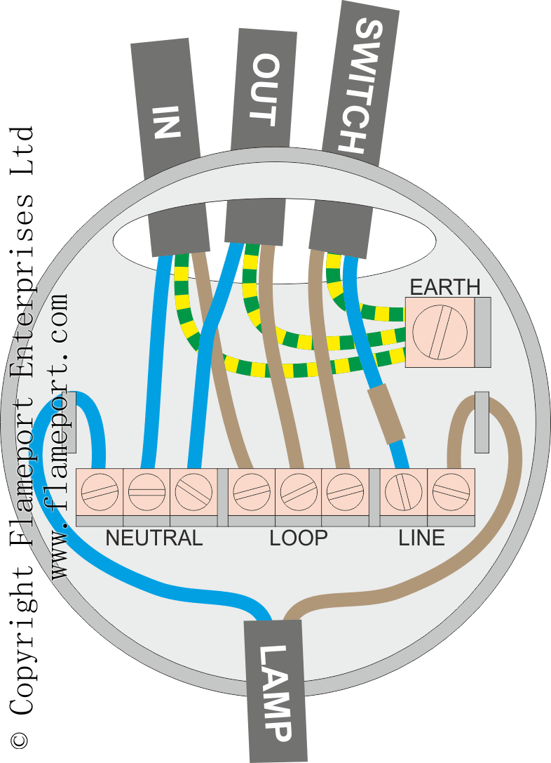
Wiring a switch loop. The purpose is the very same. Flow switch wiring diagram a newbie s overview of circuit diagrams. The black wire from the switch connects to the hot on the receptacle. Bib jun 1 15 at 1238 1 if you are working on an older home with unmarked switch loops when you trace them also mark the white wires that should be marked so that they are marked for the next time you or someone else needs to work on the circuit. The red wire going to the light switch is connected to the same terminal loop in as the red wire from the feed cable the black wire coming back from the switch is connected to the same terminal as the brown wire going to the lampholder live and the earth wire is connected to the same terminal as the earth wire from the feed cable.
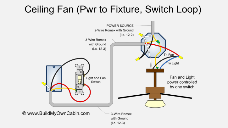
For new wiring you would run a three wire cable and use the red and black for the loop and leave the white unused and capped in the switch box. Also included are wiring arrangements for multiple light fixtures controlled by one switch two switches on one box and a split receptacle controlled by two switches. Residential electrical electrical code electrical wiring diagram electrical outlets electrical symbols electrical projects electrical engineering electrical installation electric circuit. Tamper and flow switch wiring diagrams best idem stainless steel. Getting from point a to point b. From a physical wiring standpoint it will be necessary at a minimum to run 143 cable which contains a black red and white wire.
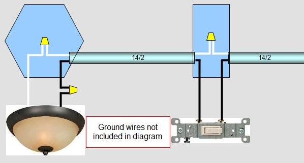
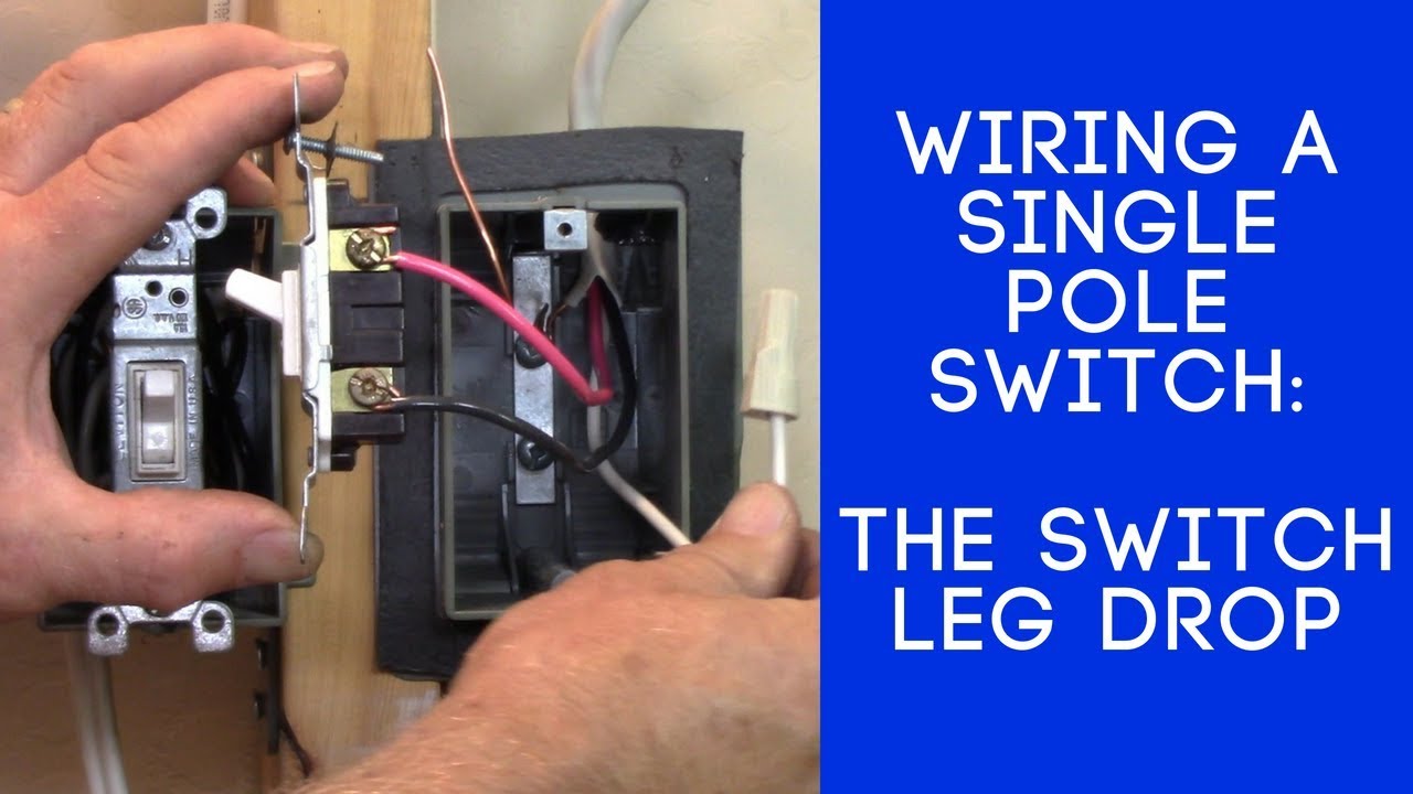
Posted on february 19 2018 august 9 2018 by headcontrolsystem. Mark the white wire at each end with black tape or black paint to indicate it is hot. This page contains wiring diagrams for household light switches and includes. Wiring a plug electrical code electrical diagram electrical wiring diagram 3 way switch wiring wire switch three way switch. Circuit electrical wiring enters the switch box the black wire power in source attaches to one of the switch screw terminals fixture wiring exits the switch box the black wire power out wiring attaches to the. Figure 2 diagram of a switch loop the 2011 nec code requires that the switch loop use wires of the proper color code to signify hot wires.
A switch loop single pole switches light dimmer and a few choices for wiring a outlet switch combo device. To make a switch loop connect the incoming hot black wire to the white neutral wire that runs to the switch. The hot source wire is removed from the receptacle and spliced to the red wire running to the switch. Diagram bacamajalah technical ideas. This wiring diagram illustrates adding wiring for a light switch to control an existing wall outlet.
Gallery of Switch Loop Wiring Diagram