Three wire cable runs from the fan to the switch box and the source neutral is spliced to the white wire and to the fan neutral. By watching this video you will be able to wire a switch loop for your ceiling fan as well.
Adding An Extra Light From A Light Switch
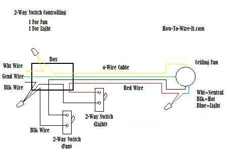
Switch loop ceiling fan wiring. Connect the blue wire to the red wire. Split the incoming hot wire into a y and connect it to a terminal on each switch. Connect the black wire to the screw located in swith 1. Connect white wires together. Connect black fan wire to the black ceiling wire. A wiring diagram is a streamlined standard pictorial depiction of an electrical circuit.
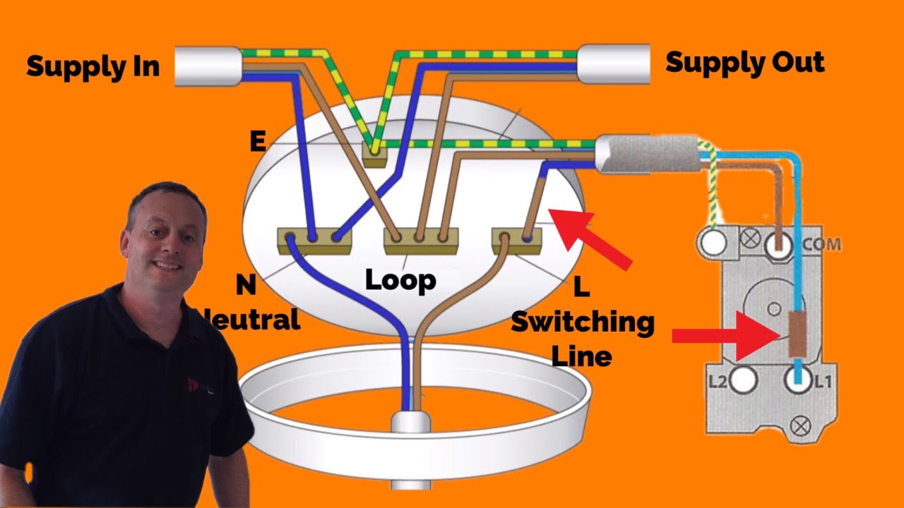
Next the incoming white neutral wire is attached to the light fixture as usual and the black wire from the switch is connected to the light fixture. Typically a green wire is attached to your fan bracket and the other green wire is attached to the fan itself. Connect the red wire to the screw in switch 2. In the switch box. Ceiling fan switch wiring diagram 2 line voltage enters the switch outlet box and the line wire connects to each switch. It reveals the elements of the circuit as simplified shapes and the power and signal connections between the tools.
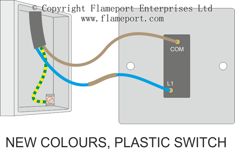
In this case the fan and light must be set to a desired mode using a pull chainchains or wireless remote and then the switch is used to turn the entire fixture on or off. This wiring configuration is a bit limiting as the fan and light are controlled from a single switch. To make a switch loop connect the incoming hot black wire to the white neutral wire that runs to the switch. Ceiling fan diagram switch loop this ceiling fan wiring diagram can be used if the power source is supplied to the fan fixture. Leave the green or copper wire thats coming out the ceiling unattached for now. Renting cabin for profit.
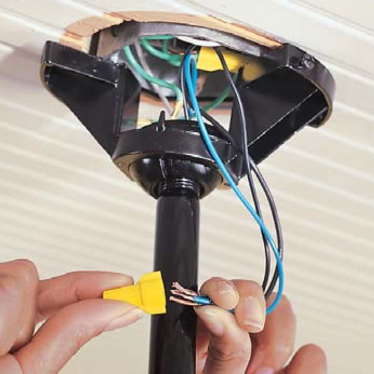
Switched lines and neutral connect to a 3 wire cable that travels to the lightfan outlet box in the ceiling. Mark the white wire at each end with black tape or black paint to indicate it is hot. Twist the copper ends of the wires together to connect them together. Wiring a ceiling fan switch loop use this wiring when the source is at the fixture and you want to control the feed to both components with the same switch. The fan control switch usually connects to the black wire and the light kit switch to the red wire of the 3 way cable. Collection of 4 wire ceiling fan switch wiring diagram.
Remember to always shut off power to the circuit before doing any work.
Gallery of Switch Loop Ceiling Fan Wiring