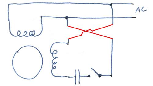
Now the torque produced is such that it gives circular movement to the rotor. Know the method used to reverse a single phase induction motor.

Split Phase Motor Electrical Engineering Centre
Split phase motor wiring diagram. Permanent split capacitor motor wiring diagram figure is a schematic diagram of a capacitor start motor. The centrifugal switch is a normally close control device that is wired into the start winding. A split phase capacitor start electric motor may be defined as a form of split phase motor having a capacitor connected in series with the auxiliary winding. Split phase capacitor start electric motor. You can save this pic file to your personal laptop. Split phase motor wiring diagram the split phase motor can be found in applications requiring 120 hp up to 13 hp meaning it can turn anything from blades on a ceiling fan washing machines tubs blower motors for oil furnaces and small pumps.
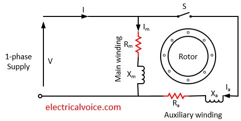
The auxiliary circuit is opened by the centrifugal switch when the motor reaches 70 to 80 percent of synchronous speed. Split phase motor diagram is shown in the figure. This is the split phase ac induction motor operation with wiring diagram of a pic i get off the asynchronous motor wiring diagrams collection. Single phase motors are not self starting as the supply voltage is not producing a rotating magnetic field. Then how do the single phase motors what we use everyday are self starting. Read here to know about the split phase motor wiring arrangement and starting method of a single phase motor.
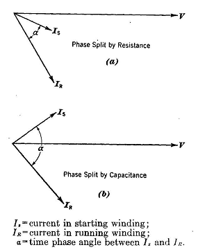
Our people also have some more illustrations connected to asynchronous motor wiring diagrams please see the picture gallery below click one of the pics then the picture will be displayed larger sized as shown above. Please right click on the image and save the graphic. This particular image. The angle between the two currents is φ as shown in the figure. I run is the current in the main winding and i start is the current in the starting winding. The schematic diagram for a permanent split capacitor motor is shown in fig.
Gallery of Split Phase Motor Wiring Diagram