All about electrical. Occasionally the wires will cross.
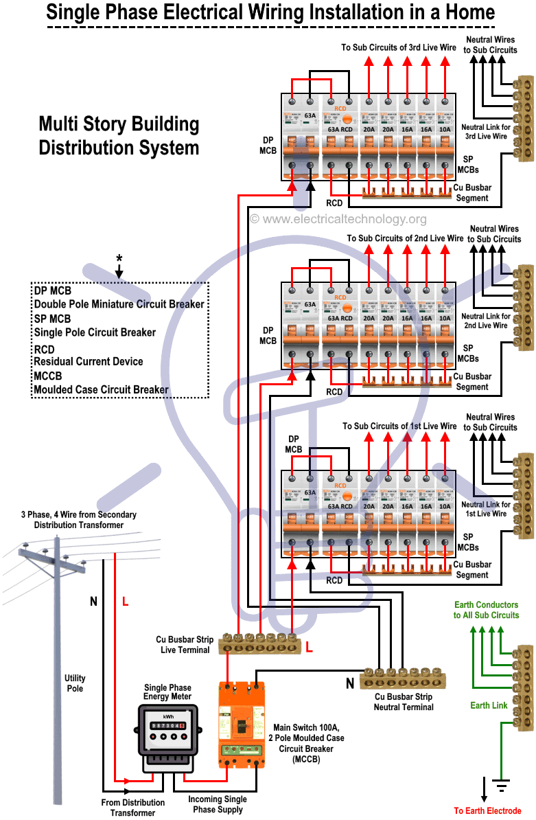
Single Phase Electrical Wiring Installation In Home Nec
Single phase wiring diagram. Electric motor internal wiring diagrams. Variety of single phase motor wiring diagram forward reverse. Injunction of two wires is usually indicated by black dot in the intersection of two lines. I have compiled a list of single phase electric motors and their wiring diagrams below. Facebook twitter linkedin tumblr pinterest reddit vkontakte whatsapp telegram share via email print. Split phase induction split.
According to earlier the lines in a single phase motor wiring diagram with capacitor represents wires. It reveals the components of the circuit as simplified shapes as well as the power and also signal connections in between the tools. Where can i find single phase electric motor wiring diagrams. Single phase motor internal wiring diagrams. Batteries wiring connections and diagrams. It includes instructions and diagrams for various types of wiring methods and other items like lights home windows etc.
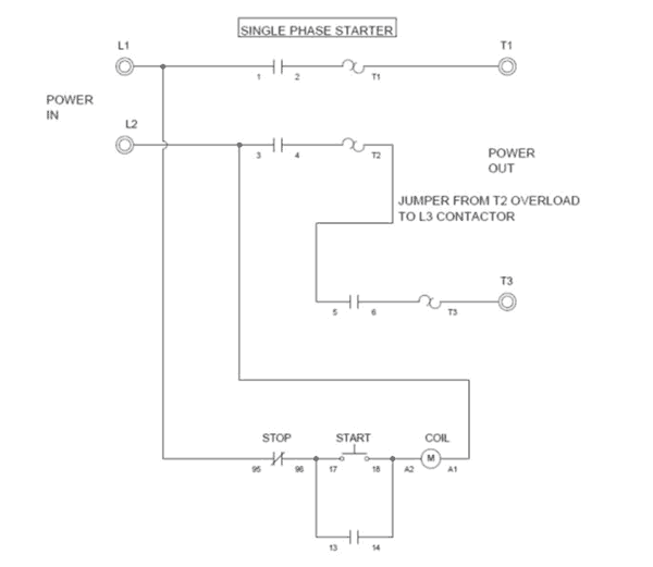
At the bottom of this post is also a video about dc shunt motors. In the above one phase motor wiring i first connect a 2 pole circuit breaker and after that i connect the supply to motor starter and then i do cont actor coil wiring with normally close push button switch and normally open push button switch and in last i do connection between capacitor start motor and contactor. Single phase motor wiring diagram with capacitor start. It reveals the components of the circuit as simplified forms as well as the power as well as signal links in between the tools. A wiring diagram is a streamlined conventional pictorial depiction of an electric circuit. How to connect single phase single phase motor wiring diagram with capacitor wiring diagram consists of many in depth illustrations that show the link of varied things.
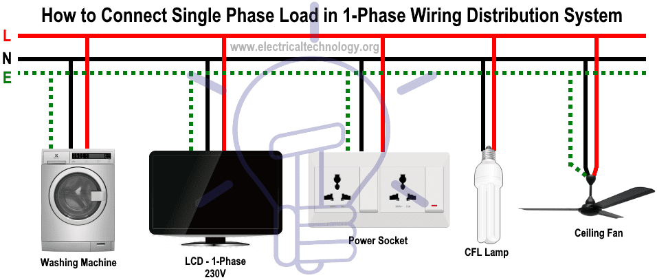
A wiring diagram is a streamlined traditional photographic depiction of an electrical circuit. Types of single phase induction motors electrical a2z single phase induction motors are traditionally used in residential applications such as ceiling fans air conditioners washing machines and refrigerators single phase motor wiring with contactor diagram the plete guide of single phase motor wiring with circuit breaker and contactor diagram. For other posts related to single phase three phase wiring diagrams check the following useful links. A wiring diagram is a simplified conventional pictorial representation of an electrical circuit. Wiring diagrams of small and fractional horsepower electric motors. It shows the elements of the circuit as streamlined shapes as well as the power and signal links in between the tools.
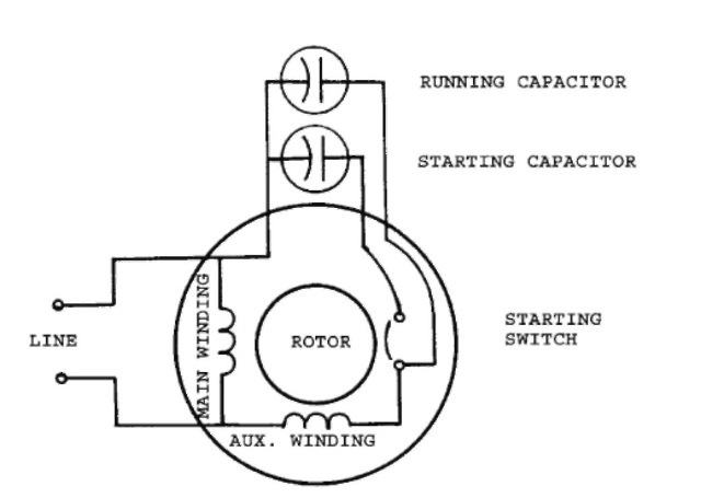
Capacitor start capacitor run induction motors are single phase induction motors that have a capacitor in the start winding and in the run winding as shown in figure 12 and 13 wiring diagram. However it does not imply link between the cables. Three phase motor power control wiring diagrams. Ups inverter wiring diagrams connection. The above diagram is a complete method of single phase motor wiring with circuit breaker and contactor. Collection of baldor single phase motor wiring diagram.
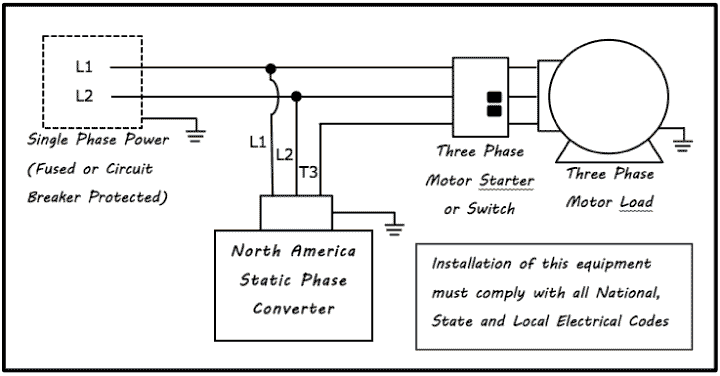
Solar panel wiring installation diagrams. Variety of 240v motor wiring diagram single phase. This type of motor is designed to provide strong starting torque and strong running for applications such as large water pumps.
Gallery of Single Phase Wiring Diagram