For example i have a fixture that says 4x36 watts fluorescent lamp. Txls should be j013724 my correction figure 5 single line reactance circuit diagram reactances shown on a per unit basis 7.
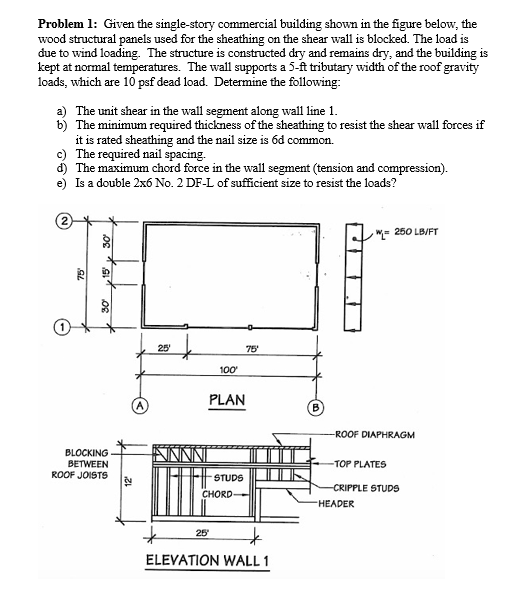
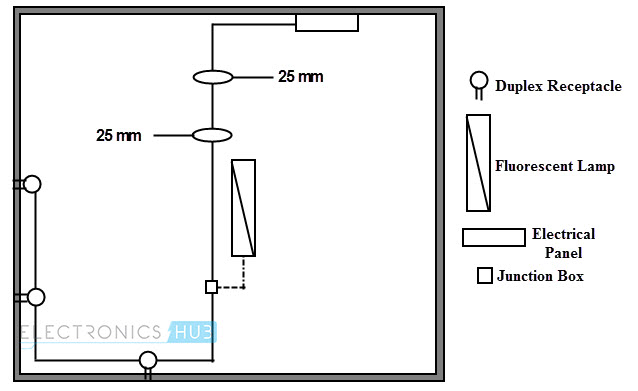
Solved Problem 1 Given The Single Story Commercial Build
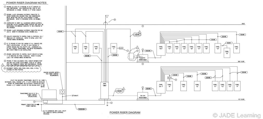
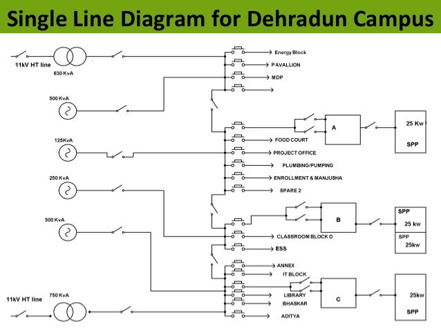
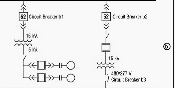
Single line diagram of commercial building. 11 single core cables size 240 mm2 each three cables per phase two for neutral mccb circuit size a two cables size 3x12070 mm2 e each lift smdb g smdb 1 smdb 2 smdb 3 supply fig6 single line diagram of a typical 1104 kv substation two cables size 3x18595 mm2 e each. It is to be noted that the elements. Connect the neutral and live wire from utility pole in the first two input slots of single phase energy meter respectively as shown in fig 1. First of all connect the single phase energy meter to the mains supply ie. Calculate operating conditions of the motors if the motors are operating at 12 kv this represents 12 kv138 kv 087 per unit voltage. Electrical one line or single line diagram.
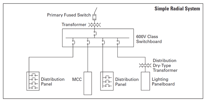
You can tell from the single line diagram that the automatic transfer switch would connect the emergency generator into the circuit to keep equipment running if power from the bus were lost. If you arent sure that how to wire a three phase energy meter then check this simple tutorial which show how to wire a single phase kwh meter digital or analog energy meter. This area of the single line diagram tells us that it is important for the equipment connected below the automatic transfer switch to keep running even if power from the bus is lost. Show the path of electricity from start to finish. Block diagrams are easy to follow and show the path of electricity from start to finish. Single line diagram 1.
As we know that the single line diagram is a simplified way for representing a 3 phase power system so in case of. The one line diagram is similar to a block diagram except that electrical elements such as switches circuit breakers transformers and capacitors are shown by standardized schematic symbols. At unity power factor. Connect the mccb moulded case circuit breaker as a two pole main switch to the incoming phase. A block diagram provides a rough outline of a circuit. It should be mentioned that one line diagrams also known as single line diagrams are used by a number of trades including hvac and plumbing but the electrical one line diagram is the most common.
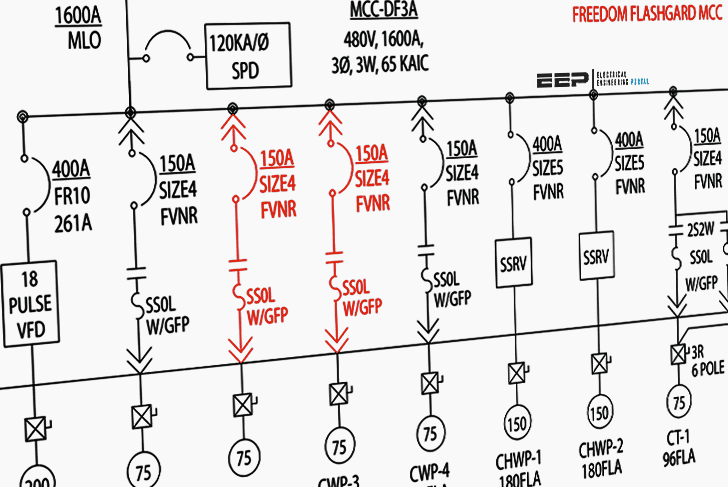
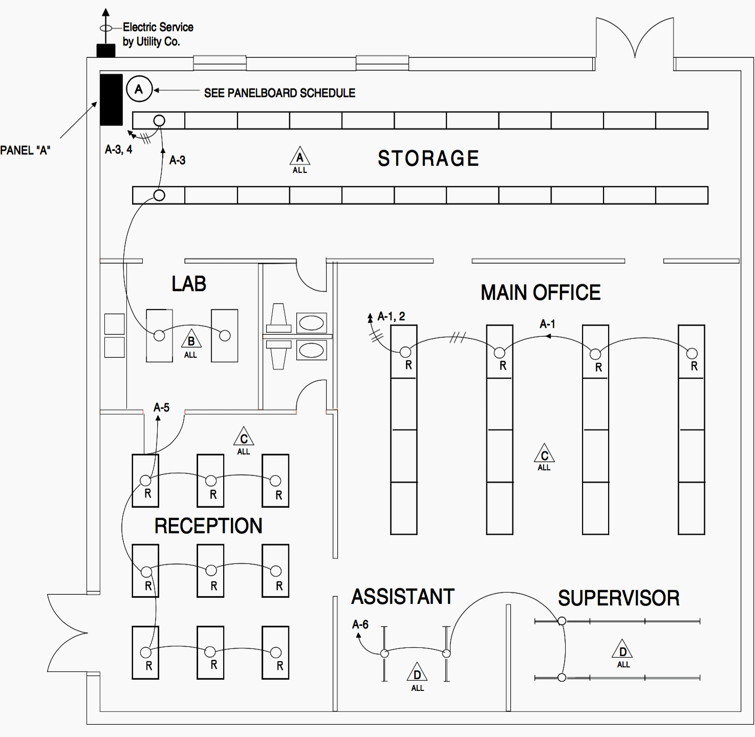
Hvac and plumbing riser diagrams are essentially one line diagrams but they go by a different name. The completed reactance diagram is shown in figure 5. A block diagram is used primarily to. My problem is that i am not sure that given that single line diagram above how to calculate the total load to be connected to a certain circuit and thus the number of fixtures to be connected. There are 5 circuits shown on the diagram. Show the major components of a system.
Single line diagrams other types of diagrams. Show the way in which these components connect to each other. So how many lamps should be connected. An electrical one line diagram is a representation of a complicated electrical distribution system into a simplified description using a single line. A one line diagram or single line diagram is a simplified notation for representing an electrical system. The electrical elements like transformer capacitor circuit breaker bus bars are represented by the standard.
A low voltage motor control circuit is attached to the automatic transfer switch through a low voltage bus. Present a general description of a system and its functions.
Gallery of Single Line Diagram Of Commercial Building