Forward green switch is use for to run motor forward and reverse switch is used for run motor on reverse mode. In the above 3 phase motor forward reverse wiring diagram.

Push Button Motor Control Circuits
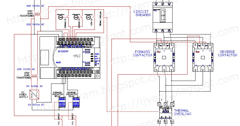
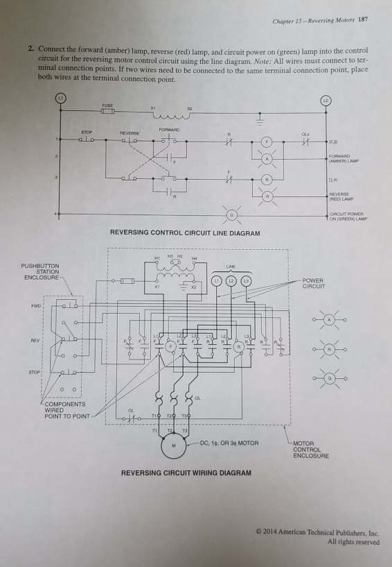
Reverse forward motor control circuit diagram. Figure 5 forwardreverse motor wiring diagram. A wiring diagram is a simplified conventional pictorial representation of an electrical circuit. How to read an electrical diagram lesson 1 duration. Hello friends today i will put video abou how to wiring diagram of reverse forward starter for three phase motor also i will shaw you control circuit diagram so that please see this video at last. From the 2nd thermal overload relay normal close contacts the supply goes to the both contactors coil contactsterminals. The red push button is for switch off the motor.
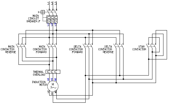
Three phase motor connection reverse and forward power and control wiring diagrams two direction one speed abbreviations. The figure given below shows the control and power diagram of forward and reverse starter diagram. These two normally open push button switch shown with green color. Ol over load relay no normally open nc normally close rev reverse for forward. In this wiring diagram both the forward and reverse coils have their returns connected to l2 and not to the overload contacts. To run the motor of above 05 hp rating circuit has to made in star delta.
The dc motor is connected to the supply through dpdt double pole double through switch by changing the switch position we can get forward and. Forward and reverse motor conrol. Variety of single phase motor wiring diagram forward reverse. In the above reverse forward motor control circuit diagram. In this website we already published about speed control of dc motor with timer ic here this circuit constructed for the basic motive to meet the forward reverse operation of dc motor with speed control. In the event of an overload both motor starter output coils will be dropped from the circuit because the plcs output to both starters will be off.
These type of starters are used in various applications eg mixing of materials dying. How to change rotation of a three phase electric motor. It reveals the components of the circuit as simplified forms as well as the power as well as signal links in between the tools. More electrical tips and diagrams wwwaboutelectricitycouk like subscribe and dont skip the ads. These forward and reverse starters are dol type and not used above the 05 hp motors. The neutral wire first goes to the thermal overload relay nc contacts and to the light indicator.
Control circuit for forward and reverse motor checkout video on 4 way switch wiring. The overload contacts are connected to l1 on one side and to the plcs input module on the other input 003.
Gallery of Reverse Forward Motor Control Circuit Diagram