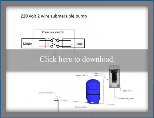
To replace the two wire pump. The green ground wire should also be terminated to the box and a ground coming from the panel.
How Do I Identify The C Terminal On My Hvac Home
Pump control panel wiring diagram schematic. Submersible pump control box wiring diagram. Posted on april 17 2018 august 9 2018 by headcontrolsystem. 1972 bronco alternator wiring diagram. Qd control box wiring diagram. Electrical wiring diagrams are comprised of 2 things. Collection of submersible pump control box wiring diagram.
Leviton decora 3 way switch wiring diagram 5603. Brushless dc electric motor diagram. Duplex pump control panel wiring diagram sample. Tda 2040 stereo schematic. It shows the elements of the circuit as streamlined forms and the power and signal. Disconnect the pump wires and tie a strong lightweight.
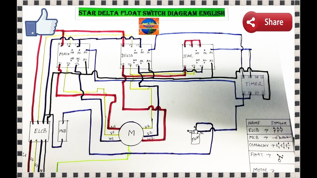
A wiring diagram is a simplified traditional photographic depiction of an electrical circuit. In which i control a three phase submersible pump motor using magnetic contactor. It shows the parts of the circuit as simplified shapes as well as the power as well as signal links between the devices. Single phase submersible pump control box wiring diagram 3 wire submersible pump wiring diagram in submersible pump control box we use a capacitor a resit able thermal overload and dpst switch double pole single throw. 1978 john deere gator. Signs that stand for the parts in the circuit and also lines that stand for the links between them.
Replace a two wire pump. The wiring connection of submersible pump control box is very simple. August 27 2017 air conditioner electrical wiring heat pump air conditioner auto ac wiring air conditioning electrical wiring central air conditioner electrical wiring home air conditioner wiring diagram wiring diagram for air conditioning unit running wiring for air conditioner units mini split electrical wiring wiring 220 air conditioner window type air conditioner air conditioner wiring schematic air conditioner control wiring diagram air conditioner wiring connection ac. After determining the voltage is zero disconnect the motor wires directly from the pressure switch box m1 and m2. The diagrams for both the two and three wire pumps can be downloaded using adobe. Wiring a 60 amp disconnect with a gfi.
Free wiring diagram menu. It shows the parts of the circuit as simplified forms. Pump control panel wiring diagram schematic just whats wiring diagram. A wiring diagram is a simplified traditional photographic depiction of an electric circuit. Here is the complete guide step by step. Check both sides of the switch to confirm zero voltage and you are ready to remove the pump.
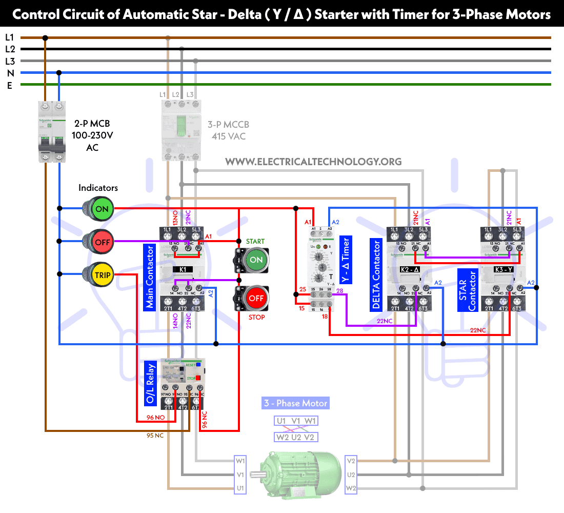
Attractive pump control panel wiring diagram model electrical. In the diagram i showed the 3. Today i am here to share with you the 3 phase submersible pump wiring diagram. A wiring diagram is a kind of schematic which makes use of abstract photographic signs to show all the interconnections of components in a system. Variety of duplex pump control panel wiring diagram. Stratton 12hp startet nicht.
Not only a contactor but also i install the thermal overload relay which will protect the motor form burning in case of over current flow to the circuit. Assortment of pump control panel wiring diagram schematic. Duplex pump control panel wiring diagram fresh goldstar gps wiring. September 3 2018 january 22 2019 by larry a. A wiring diagram is a streamlined traditional pictorial depiction of an electric circuit. From wiring diagrams you understand the relative location of the components and also just how they are linked.
Well pump control box wiring diagram awesome wonderful franklin. Holly electric choke wire diagram.
Gallery of Pump Control Panel Wiring Diagram Schematic