Rani gunj hyderabad 5 2 366 dy. When current starts flowing through the control coil the electromagnet starts energizing and thus intensifies the magnetic field.

Gibson Gss 100 Wiring Diagram Wiring Diagram
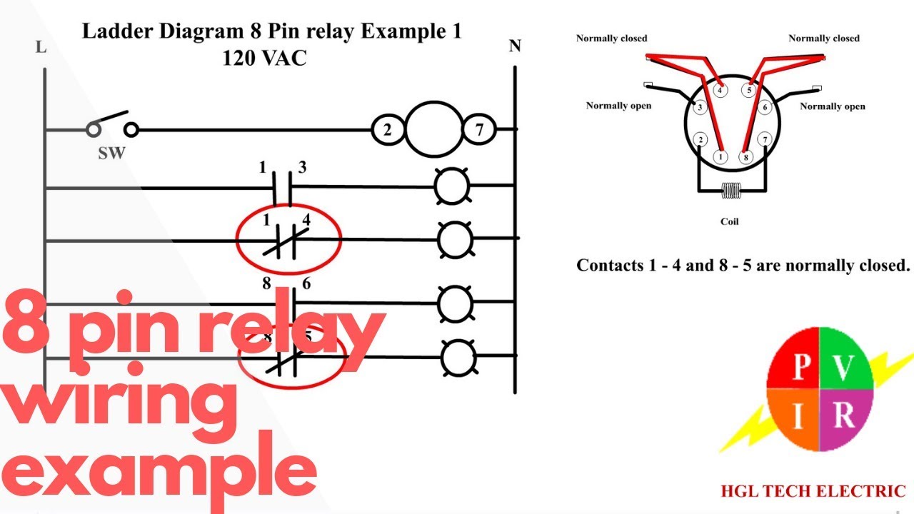
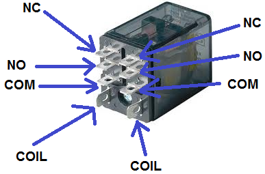
Iec255 relay wiring diagram. As you can see there is absolutely no difference between the square type and the round type other than the ratings on the relay. The com terminal is the common terminal. Actual wire colors differ by country andor voltage. An iron core is surrounded by a control coil. Outlet with 4 wires. Thus the upper contact arm starts to be attracted to the lower fixed arm and thus closes the contacts causing a short circuit for the power to the.
The polarity of the voltage does not matter. Mohan tower 202 2nd floor rani gunj hyderabad 500003 dist. Collection of time delay relay wiring diagram. Electric dryer plug 3 prong. Dimmer light switch gets. Omron relay is an electrical device such that current flowing through it in one circuit can switch on and off a current in a second circuit.
The diagram shows an inner section diagram of a relay. This pinout image is only a 2 pole diagram for room on the page purposes but you can get the picture here with this one since a 3 pole will just have 1 more set of contacts. As shown the power source is given to the electromagnet through a control switch and through contacts to the load. It is temporary magnet made by coiling wire around an iron core when current flows in the coil the iron becomes a magnet. Dielectric strength. N4jte vertical array.
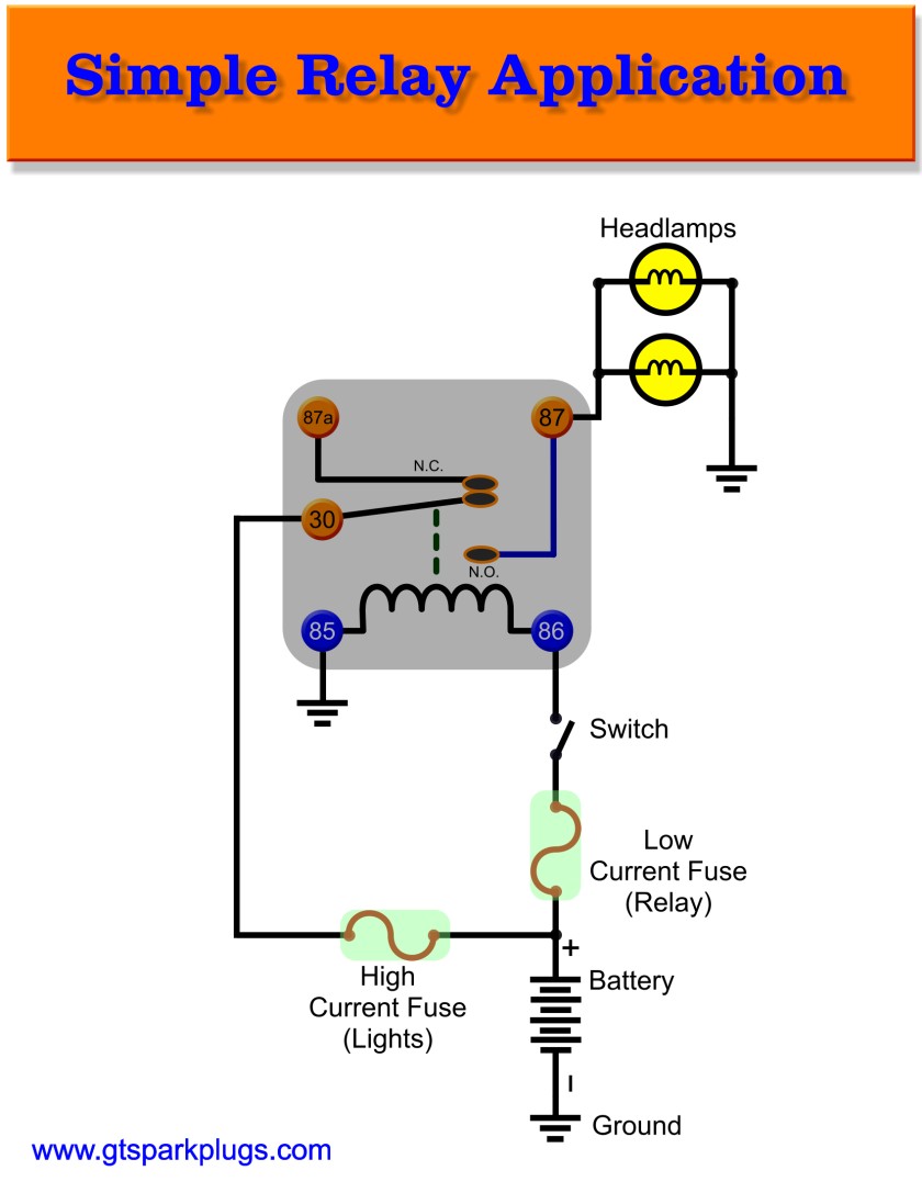
A positive and negative voltage can be placed on either end. Dpdt relay wiring diagram how to build a relay driver circuit types of relays relay terminals relay wiring diagrams. Dpdt relay wiring diagram. Black line red load grey neutral green earth ground blue ethernet important. If the coil terminals are energized. Electric fan connection using fan relay kit duration.
When the relay receives 12 volts of power the relay snaps from the nc position to the no position. This is the diagram below to learn all the pin terminals of a double pole double throw dpdt relay. How to hook up a light switch. The red led and the dc fan now shut off and the green led and the dc motor now turn on and operate. Hunter thermostat not turning on furnace. How to wire a relay and why you should use them.
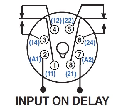
12vdc 3 way switch. The square relay pinout shows how the relay socket is configured for wiring. How to wire tail lights. Many variations possible through a selection of operation indi cators mechanical and led indicators lockable test button built in diode and cr surge suppression bifurcated contacts etc. Arc barrier standard on 4 pole relays. Otherwise they work exactly the same.
Polarity only matters if a diode is used. The 2 coil terminals is where the voltage is placed in order to energize the coil. Place the relays rated coil voltage on these terminals. How to connect a dpdt relay in a circuit. General purpose relay my new model 1 general purpose relay my new model versatile and function filled miniature power relay for sequence control and power switching applications models with lockable test buttons now available. Din rail 8 channel relay switch wiring guide supported model c4 din 8relsw e din rail 8 channel relay switch diagrams color code.
Time delay relay wiring diagram wiring diagram timer relay fresh wiring diagram time delay relay valid glow relay wiring diagram. Click on the image to enlarge and then save it to your computer by right clicking. The wire colors shown in figure 1 in the diagrams color code table are examples only. Broke bastard garage 515561 views. Wiring diagrams use these control4 din rail 8 channel relay switch wiring diagrams along with the din rail 8 channel relay switch.
Gallery of Iec255 Relay Wiring Diagram