We show our ac power source on the left with l1 and n coming out of it our switch to the top and our light to the left. To begin understanding how to read and understand electrical circuit diagrams take our basic circuit and draw it out as it would physically be wired.

How To Follow An Electrical Panel Wiring Diagram Realpars
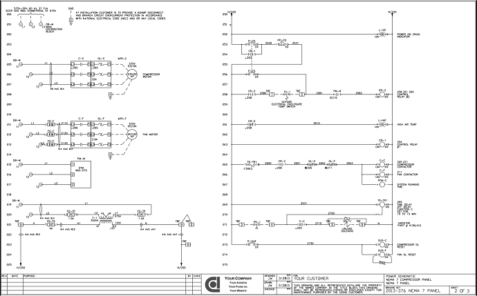
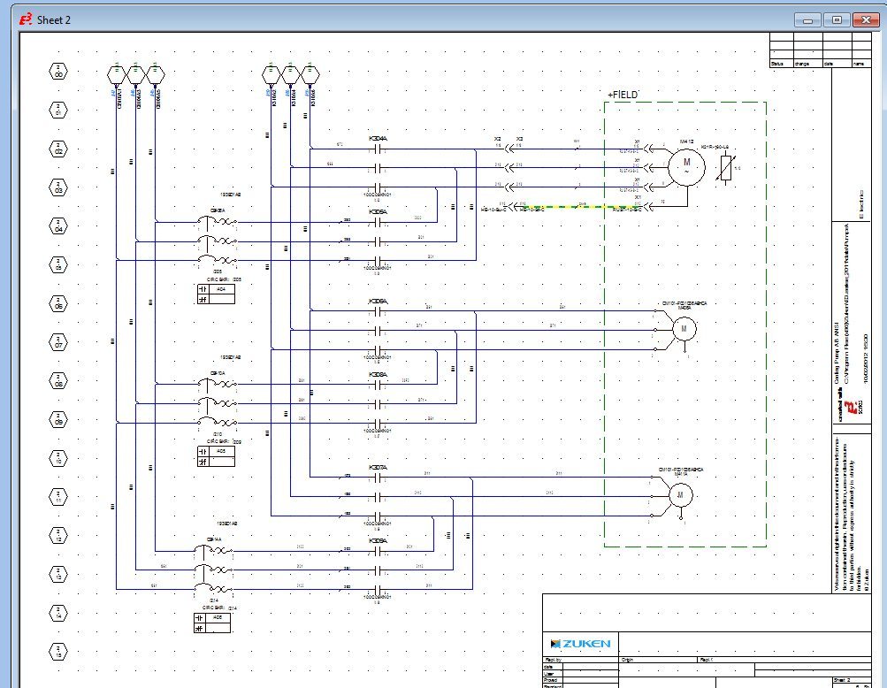
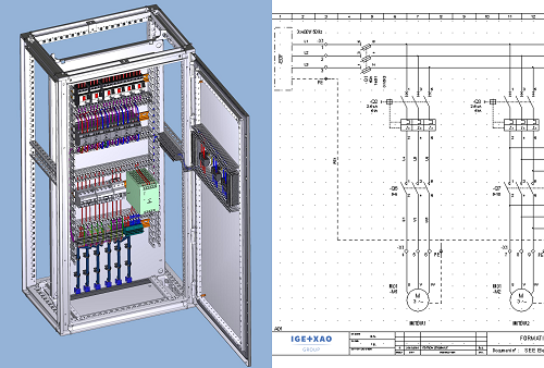
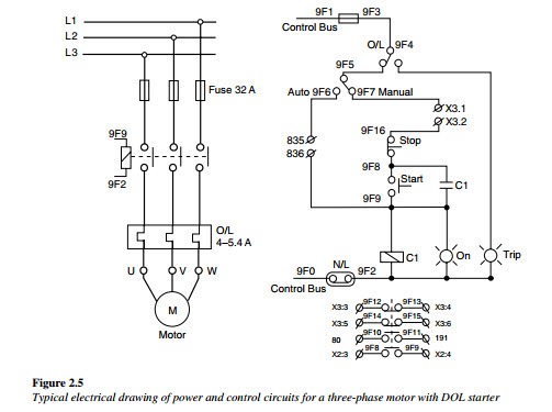
How to read electrical control panel drawings. Figure 5 below shows a schematic diagram for a plc based motor control system similar to the previous motor control example. 5 things you need to know before designing your motor control center. Whether its a simple home appliance or a control panel wiring diagram most systems and devices will include power supplies a ground and switches. Wiring diagrams show the components of a system as well as their connections. Power riser diagrams to show the service entrance and panelboard components. But it does tend to become more complex.
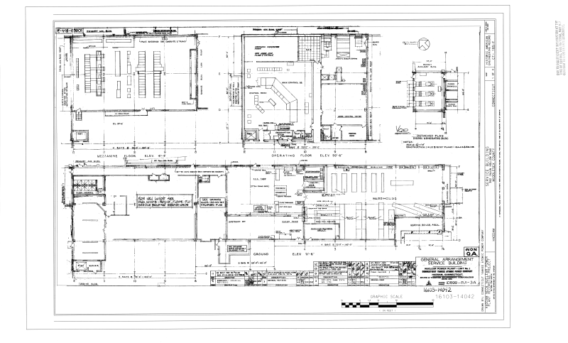
83 automatic selective control or transfer relay 84 operating mechanism 85 carrier or pilot wire receiver relay 86 lockout relay 87 differential protective relay 89 line switch 90 regulating device 91 voltage directional relay 92 voltage and power directional relay 94 tripping or trip free relay b bus f field g ground or generator n neutral t transformer. Basics 2 72 kv bus 1 line. Electrical panel emt run armoured cable run bx 4x4 junction box 10 12 21 mm 21 mm figure 2circuit drawing line diagram. A lampis usually represented as a circle with a cross inside it. Electrical basics sample drawing index basics 1 overall plant 1 line. Switchesare symbolized by an opening or break in the line.
A one line diagram or single line diagram is a simplified notation for representing an electrical system. So this is how easy it is to read the wiring diagram for a control panel. Schedules notes and large scale details on construction drawings. Try to remember these from the previous realpars article about reviewing the basics of an electrical control panel. To be able to read electrical as well as other types of drawings one must become familiar with the meaning of symbols lines and abbreviations used on the drawings and learn how to interpret the message conveyed by the drawings. The switch is connected.
When the current passes through the lamp it will produce light. Knowing the meanings of basic electrical symbolsin your electrical drawing will help you quickly understand and troubleshooting the circuit. All the wiring that you see in the panel is done based on the wiring diagram. Control panel diagrams however. This figure shows the e stop wired to cutoff power to all of the devices in the circuit including the plc. This is what we draw using autocad electrical.
Control wiring schematic and single line diagrams. When including a plc in the ladder diagram still remains. So to sum it all up here is what we learned in this article. Each page of the wiring. The one line diagram is similar to a block diagram except that electrical. It goes exactly the same for the other switches that we have here as well.
Power comes out of l2 to the switch which when open breaks the circuit preventing current flow and when closed ties the left and the right terminals of the switch together allowing current flow.
Gallery of How To Read Electrical Control Panel Drawings