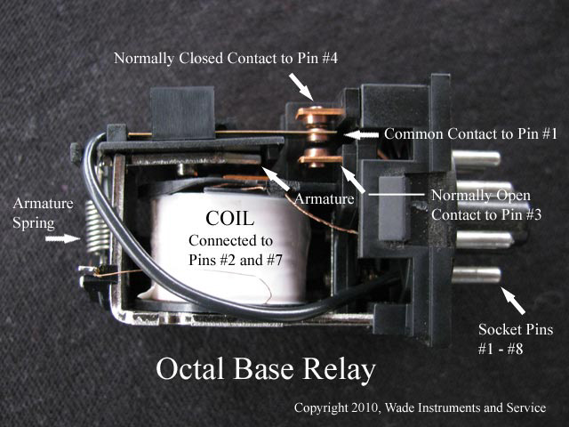
The dual purpose finder test button can be used in two ways. When the test button is released the contacts return to their former state.

39 Series Masterinterface Relay Interface Modules Emr Or
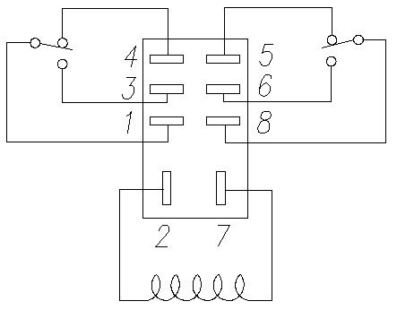
Finder relay wiring diagram. Adequate contact separation in at least one contact so as to provide functional safety. Today it makes over 12500 different products including step relays light dependent relays and other products for residential and commercial applications. 13 series electronic step relays wiring diagrams 1381 and 1391 type 1381 3 wire connection red led indication. This is also called 8 points glass type relay. For wiring diagrams see page 8 nominal voltage u n. Continuous relay on blinking relay off type 1381 4 wire connection red led indication.
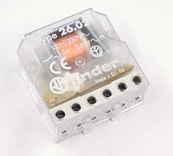
Since 1954 when it was founded finder has concentrated its efforts on the manufacture of quality products. Otherwise they work exactly the same. Type 02600 sealed construction 75 cm insulated flexible wire termination. A 8 pin relay wiring diagram or 8 pin finder type relay connetion diagram. Module for use with illuminated push buttons wiring diagrams n l 20 series modular step relays 16 a n l example. Case 2the plastic pip is broken off using an appropriate cutting tool.
All finder relays comply with this class of disconnection. A wiring diagram is a simplified traditional pictorial depiction of an electrical circuit. Interruption of a circuit without any specific requirements for distance or dielectric strength across the contact gap. It must be connected in parallel to the coil of the relay. The square relay pinout shows how the relay socket is configured for wiring. Continuous relay on blinking relay off l n l n sheet of marker tags for type 1312 and 1381 plastic 72 tags 6x12 mm 06072 adaptor for panel mounting for type 1301 35 mm wide 01101 adaptor for panel mounting for type 1312 and 1381 175 mm wide 02001 accessories 01101.
230 v ac supply voltage. This pinout image is only a 2 pole diagram for room on the page purposes but you can get the picture here with this one since a 3 pole will just have 1 more set of contacts. 5 6 7 9 12 14 18 21 24 28 36 48 60 90 110 125 v dc with the agsno 2 material the maximum peak current is 120 a 5 ms on normally open contact. Same effect can be achieved by wiring two single contacts in series. In this case in addition to the above function when the test button is pushed and rotated the. 30110220 v a minimum switching load mw vma standard contact material supply.
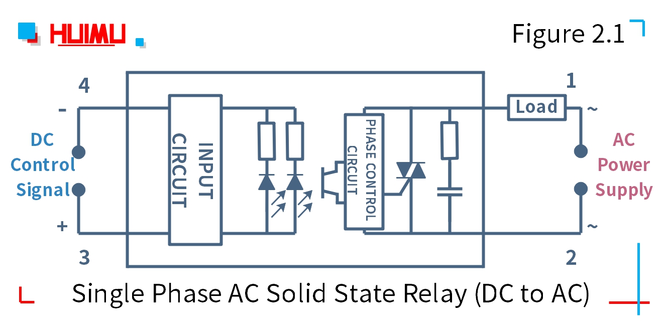
10 a general purpose relay. Relay socket wiring diagram with control signal relay socket wiring diagram for outline drawing see page 26 contact specification contact configuration see 56t series relays see 46t 55t 56t series relays rated currentmaximum peak current a rated voltage maximum switching voltage v ac rated load ac1 va rated load ac15 230 v ac va single phase motor rating 230 v ac kw breaking capacity dc1. A dielectric strength requirement must be achieved across the contact gap. Case 1 the plastic pip located directly above the test button remains intact. As you can see there is absolutely no difference between the square type and the round type other than the ratings on the relay. Copper side view see general technical information guidelines for automatic flow solder processes page ii.
All finder relays comply or exceed this. Industrial relays miniature and ultra slim relays power relays timers relay sockets and accessories. Example of wiring diagram of type 02600 this module is necessary when using between 1 and a maximum of 15 illuminated push buttons in the coil circuit each 15 ma max 230 v ac. In this case when the test button is pushed the contacts operate. Assortment of 12 volt relay wiring diagram. 5 mm contact pin pitch 1 pole 16 a pcb or 95 series sockets features 4061 1 pole 16 a 5 mm pin pitch 40xx6 bistable versions.
24 v ac supply voltage. It reveals the components of the circuit as simplified shapes and also the power and signal connections in between the tools.
Gallery of Finder Relay Wiring Diagram