Basics 6 72 kv 3 line diagram. Industrial single line diagram.
Rooftop Solar Drawings Free Trial Promotion Code Solar Pv Free
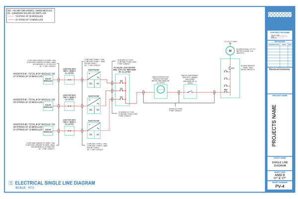
Electrical single line diagram sample. All transmission lines distributions lines and power transformers are also three phases in nature. Basics 2 72 kv bus 1 line. Basics 9 416 kv pump schematic. Basics 14 aov. Electrical basics sample drawing index basics 1 overall plant 1 line. Basics 8 aov elementary block diagram.
It is the first step in preparing a critical response plan allowing you to become thoroughly familiar with the electrical transmission system layout and design. A single line diagram also referred to as a one line diagram is usually a single page document that represents a facilities electrical distribution infrastructure. Establish base voltage through the system by observation of the magnitude of the components in the system a base value of apparent power s is chosen. Our electrical power systems primarily contain three phases of ac circuits. In this post youll learn what is single line diagram and why do we need it. It should be of the general magnitude of the components and the choice is arbitrary.
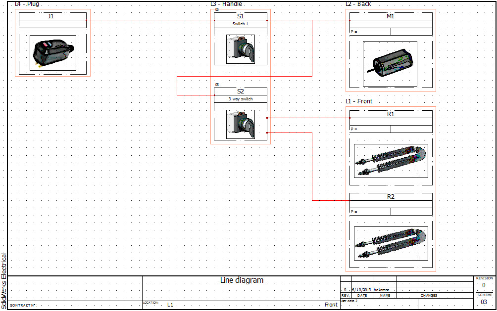
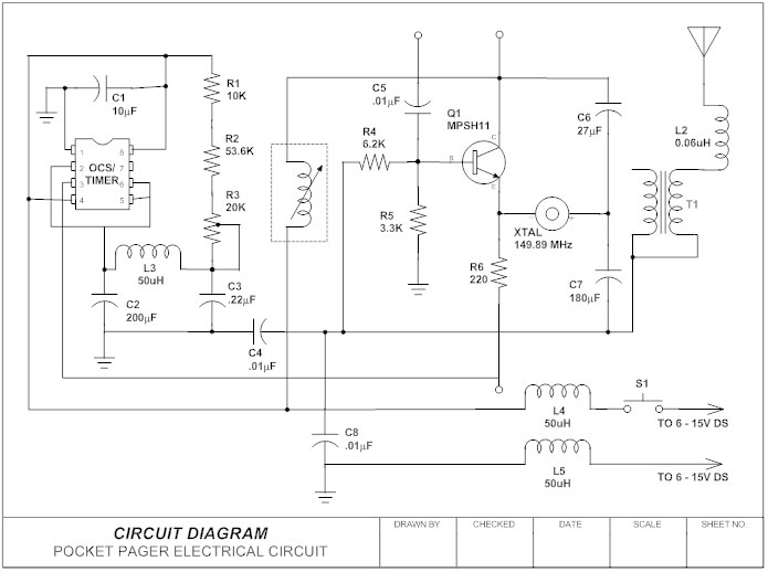
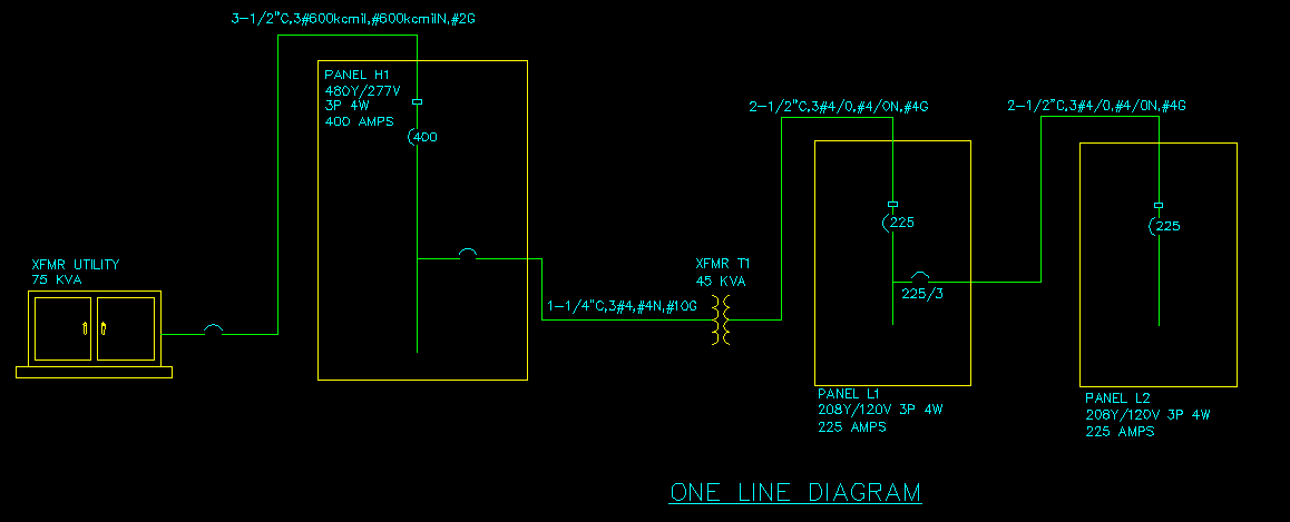
Instead of representing each of three phases with a separate line or terminal only one conductor is represented. Specifications are given in above table. A one line diagram or single line diagram is a simplified notation for representing an electrical system. Basics 7 416 kv 3 line diagram. Basics 11 mov schematic with block included basics 12 12 208 vac panel diagram. A single line diagram or sld is a simple visual representation of three phase power systems.
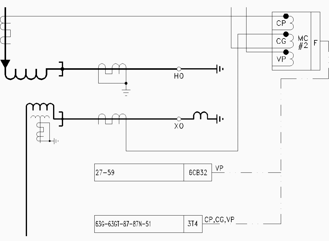
Between the generating stations and the distribution stations three different levels of voltage transmission sub transmission and distribution level of voltage are used. In this problem 25000 kva is chosen as the base s and simultaneously at the generator end 138 kv. The one line diagram is similar to a block diagram except that electrical elements such as switches circuit breakers transformers and capacitors are shown by standardized schematic symbols. Figure 4 single line diagram of electric power system supplying motor loads. Basics 13 valve limit switch legend. It will have one single line shown for bus or cable to represent all three phases.
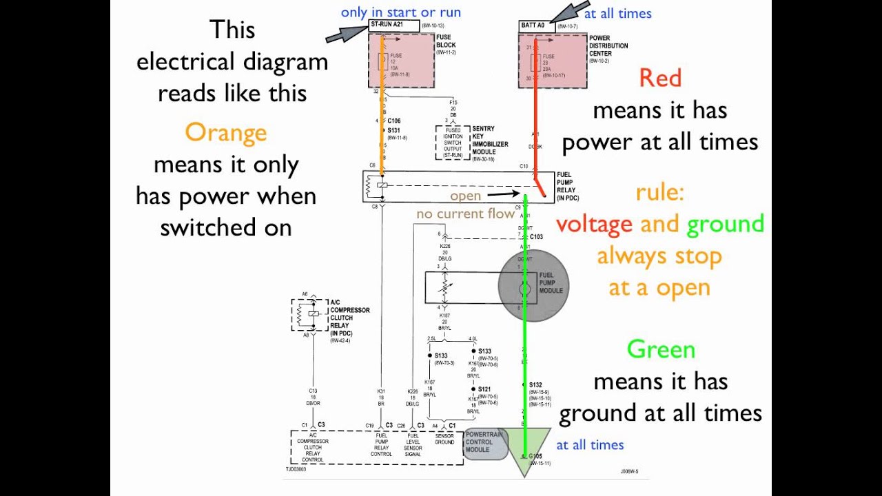
The electricity flows from the negative side of the battery through the resistors to the positive side of the battery. As a layman view sld is nothing but consisting of various components of the electrical system like transformer dg panels consisting of ht breaker lt breaker ct pt. Basics 4 600 v 1 line. Calculation procedure in 8 steps 1. Basics 3 416 kv bus 1 line. Electrical elements such as circuit breakers transformers capacitors bus bars and conductors are shown by standardized schematic symbols.
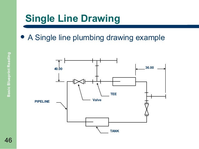
The single line diagram also becomes your lifeline of information when updating or responding to an emergency. The one line diagram has its largest application in power flow studies. Single line diagram of power supply system the electrical energy is produced at generating stations and through the transmission network it is transmitted to the consumers. The single line diagram is the blueprint for electrical system analysis. Basics 10 480 v pump schematic. Figure 1 simple single line diagram you can tell by the symbols that this single line diagram has three resistors and a battery.
Basics 5 480 v mcc 1 line.
Gallery of Electrical Single Line Diagram Sample