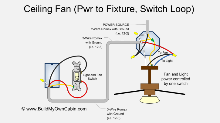
When the electrical source originates at a light fixture and is controlled from a remote location a switch loop is. 1a this is the most common loop in wiring arrangement you are likely to see.
Loop Electrical Wiring Diagram Wiring Library
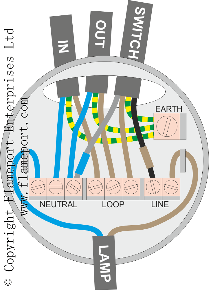
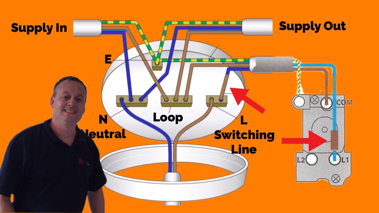
Electrical loop wiring diagram. Wiring a switch loop. One cable lne either from the mains board or the last ceiling rose one cable lne out to the next ceiling rose and one cable lsl e that goes to the wall or pull switch within that room. Also included are wiring arrangements for multiple light fixtures controlled by one switch two switches on one box and a split receptacle controlled by two switches. Electrical works wiring vasu 86 views new. The feed cable comes from a previous ceiling rose or from the consumer unit the red wire is connected to the middle terminal block loop in the black wire is connected to the same terminal block as the blue wire going to the lampholder neutral and the earth wire is connected to the earth terminal. Video explains the connection required within the ceiling rose one way switch and.
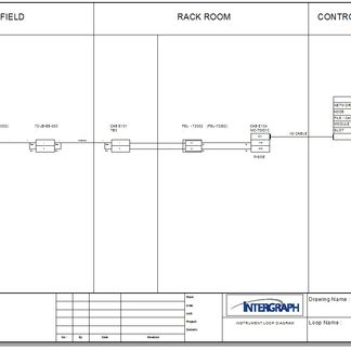
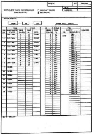
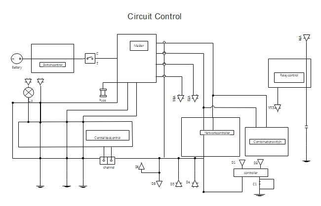
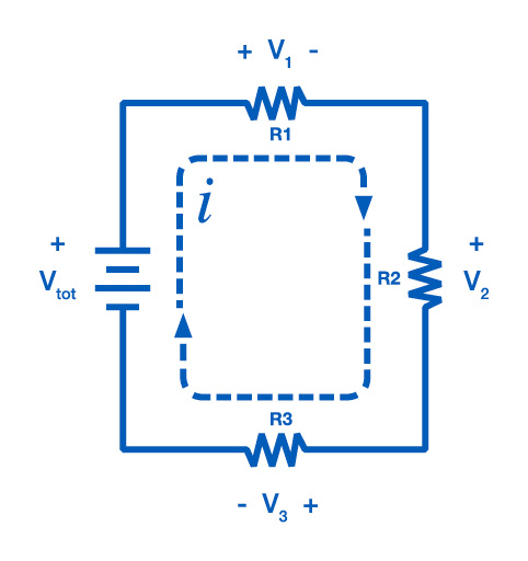
It shows three cables. Student training aid for the connections required to wire a lighting circuit using the 3 plate loop in method. Piping and instrumentation pid diagram shows the several instrumentation loops connected with particular equipment. Pid shows the signal path of instruments and gives an overall picture of the connected loops in the system whereas instrument loop diagram gives a clear idea of the instrument connected with the system. This page contains wiring diagrams for household light switches and includes. A simplified conventional pictorial representation of an electrical circuit.
Dashed lines in instrument drawings represent individual copper wires rather than whole cables. Basics of instrument loop diagrams they show all the instruments in a control loop each instrument bubble in a loop diagram represent an individual device with its own terminals for connecting wires. Electrical house mains board wiring and isolator to mcbs connection in wiring before purpose hindi duration. It shows the components of the circuit as simplified shapes and how to make the connections between the devices. The black wire from the switch connects to the hot on the receptacle. Next the incoming white neutral wire is attached to the light fixture as usual and the black wire from the switch is connected to the light fixture.
The hot source wire is removed from the receptacle and spliced to the red wire running to the switch. The earth wire must be covered with greenyellow sleeving. A switch loop single pole switches light dimmer and a few choices for wiring a outlet switch combo device. Mark the white wire at each end with black tape or black paint to indicate it is hot. To make a switch loop connect the incoming hot black wire to the white neutral wire that runs to the switch. Wiring diagram or pictorial.
The source is at the outlet and a switch loop is added to a new switch. This wiring diagram illustrates adding wiring for a light switch to control an existing wall outlet.
Gallery of Electrical Loop Wiring Diagram