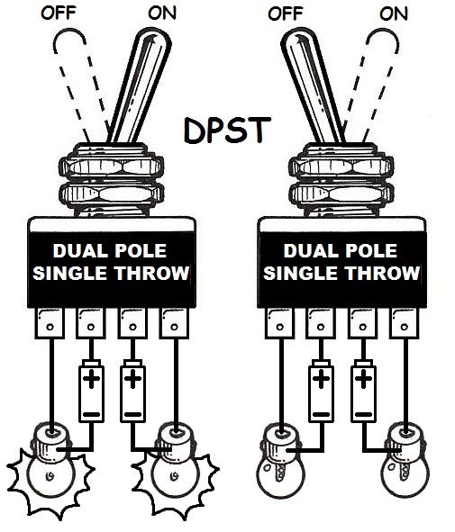
Wire a dpdt rocker switch for reversing polarity. A double pole single throw dpst switch controls the connections to two wires at once where each wire only has one possible connection.
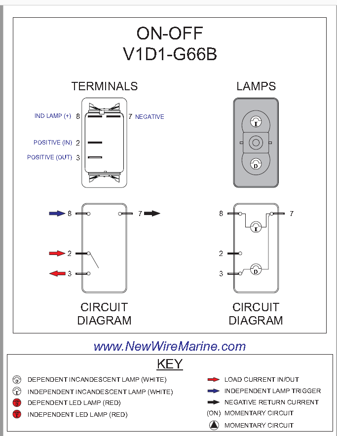
Rocker Switch Wiring Diagrams New Wire Marine
Dpst toggle switch wiring diagram. A wiring diagram is a simplified conventional pictorial depiction of an electrical circuit. Terminal 1 is connected to one load or accessory terminal 3 is connected to another load or accessory. A dpdt toggle switch has 6 terminals. How switches work spst spdt dpst dpdt simply put duration. The switch is always making one of the two connections and flips between them. You can see above how a double pole single throw switch can be used to put a circuit in any of 1 of 2 modes.
The other position of the handle is off. Double pole single throw switch dpst circuit. Throw refers to the extreme position of the actuator. It shows the parts of the circuit as streamlined shapes and also the power and also signal connections between the gadgets. In other words its like two simple switches controlled by a single actuator. St switches close a circuit at only one position.
2 methods are explained with associated wiring diagrams. A double pole double throw switch is used for this purpose but you have to wire it up correctly. Switches with two pilot lights. We will now go over the wiring diagram of a dpdt toggle switch. How to wire your dpdt switches for your uur kits. Dt switches close a circuit in the up position as well as the down position on on.
When the switch is connected one way for circuit a and circuit b the lamp and led will both be on. The dpst switch for example has four terminals but it is a dp not a 4p switch. How to reverse a dc motor with a toggle switch. Assortment of dpst rocker switch wiring diagram. Here is a diagram of a spdt toggle switch. When you need to control a dc motor such as a dc linear actuator you usually need to be able to swap the polarity on the wires going to the motor.
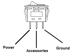
Terminal 2 is connected to power. In this video i give you the characteristics of a dpdt switch and how to wire. Terminals 3 and 4 represent the toggle switch. This is how you wire a double pole double throw dpdt switch. Below is the schematic diagram of the wiring for connecting a dpdt toggle switch. Below is an example of a circuit which utilizes a double pole single throw switch.
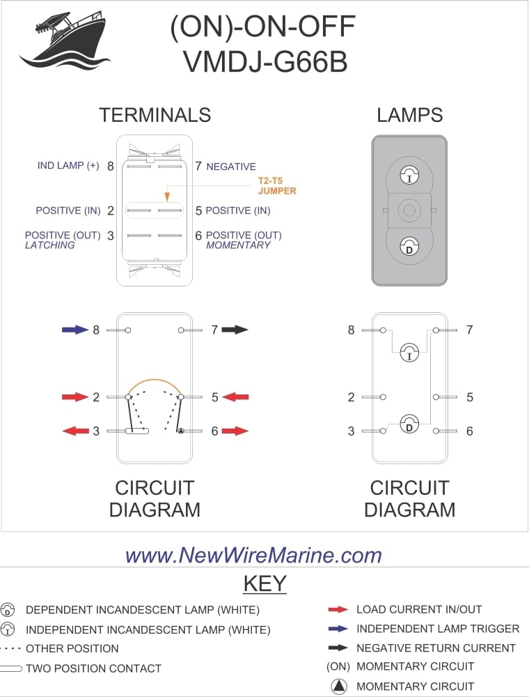
Dpdt toggle switch wiring. To convert connect jumper wire from terminal 3 to terminal 6 and connect terminal 4 to ground diagram f diagram g1 diagram g2 b l 2 4 3 b l 2 4 36 b l 2 4 36 jumper single pole sp double pole dp switch wiring diagrams diagrams represent both momentary contact or maintained contact switches.
Gallery of Dpst Toggle Switch Wiring Diagram