It was introduced commercially in 1989 and became ieee standard 8023 in 1983. Every electrical component such as a resistor capacitor and inductor has a standard symbol.

What Is An Electrical Diagram And What Are The Different
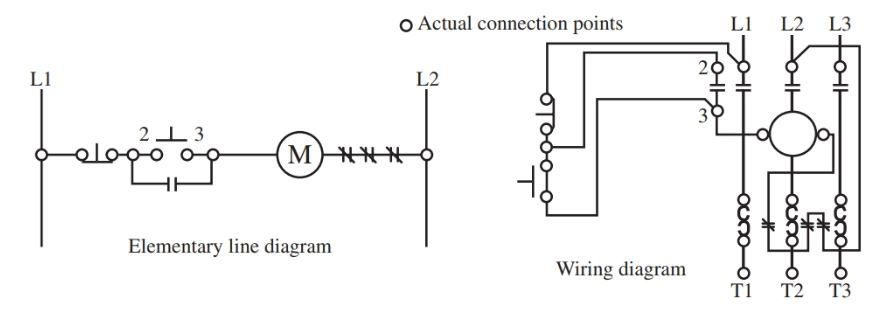
Difference between schematic and wiring diagram. A schematic diagram focuses more on comprehending and spreading information rather than doing physical. Typically they are designed for end users or installers. A proper wiring diagram will be labeled and show connections in a way that prevents confusion about how connections are made. Schematics are symbolic representations of complete circuits or systems created during the design phase. This article illustrates the differences between schematic diagrams and circuit diagrams and it may benefit you a lot in identifying the components of an electric system tracing a circuit and even fixing electrical equipment. For detailed notes please visit at httpzenmuraliblogspotin electrical diagrams part 02 difference between pictorial and schematic diagram.
What is the difference between a schematic a wiring diagram. Schematic is a synonym of diagram. Diagram is a synonym of schematic. As a verb diagram is to represent or indicate something using a diagram. In some cases the schematic symbol and the wiring diagram symbol are the same. A wiring diagram is sometimes helpful to illustrate how a schematic can be realized in a prototype or production environment.
Differences between publications so it is important to compare between diagrams schematics or illustrations the contents of this product were extracted from. As nouns the difference between schematic and diagram is that schematic is a drawing or sketch showing how a system works at an abstract level while diagram is a plan drawing sketch or outline to show how something works or show the relationships between the parts of a whole. Schematic diagrams a schematic or schematic diagram represents the elements of a system with abstract and graphic symbols instead of realistic pictures. A wiring diagram is sometimes helpful to illustrate how a schematic can be realized in a prototype or production environment. 1972 wiring and vacuum diagrams form fd 7795p 72 19651972 ford car master parts and accessory catalog form fp 7635b 1972 car shop manual volume iii form 7098 72 3 and doc 98 ford escort engine diagram 98 ford escort engine diagram 98 ford escort engine diagram wiring vacuum diagrams manufactures of ford shop diagram. Typically they are designed for end users or installers.
A proper wiring diagram will be labeled and show connections in a way that prevents confusion about how connections are made. This article shows how to wire an ethernet jack rj45 wiring diagram for a home network with color code cable instructions and photosand the difference between each type of cabling crossover straight through ethernet is a computer network technology standard for lan local area network. Many wiring diagrams also have a key that provides important information such as wire gauge and colours. As a adjective schematic is represented simply. Wiring diagrams for circuits use the same labels as the schematic.
Gallery of Difference Between Schematic And Wiring Diagram