Modern cooling fan circuitry has advanced a great deal and is now as complex as any other side of the automotive electronic industry. Peugeot 206 cc wiring schematic wordpresscom wiring diagrams engine cooling fan temp peugeot 206cc 2001 engine fuse box peugeot 206 fuse diagram peugeot 207 wiring diagram for peugeot 1600 gti engine diagram of peugeot boxer diesel the main power in for your peugeot should be switched so the correct adapter will associate this starters alternators 41 peugeot 42 proton 43 renault 44 rover 45 saab 46 subaru 47 suzuki 48 toyota 99 universal car brand car brand product group 100 engine.

Ceiling Fan Wiring Diagram 1 Electrical Wiring Home
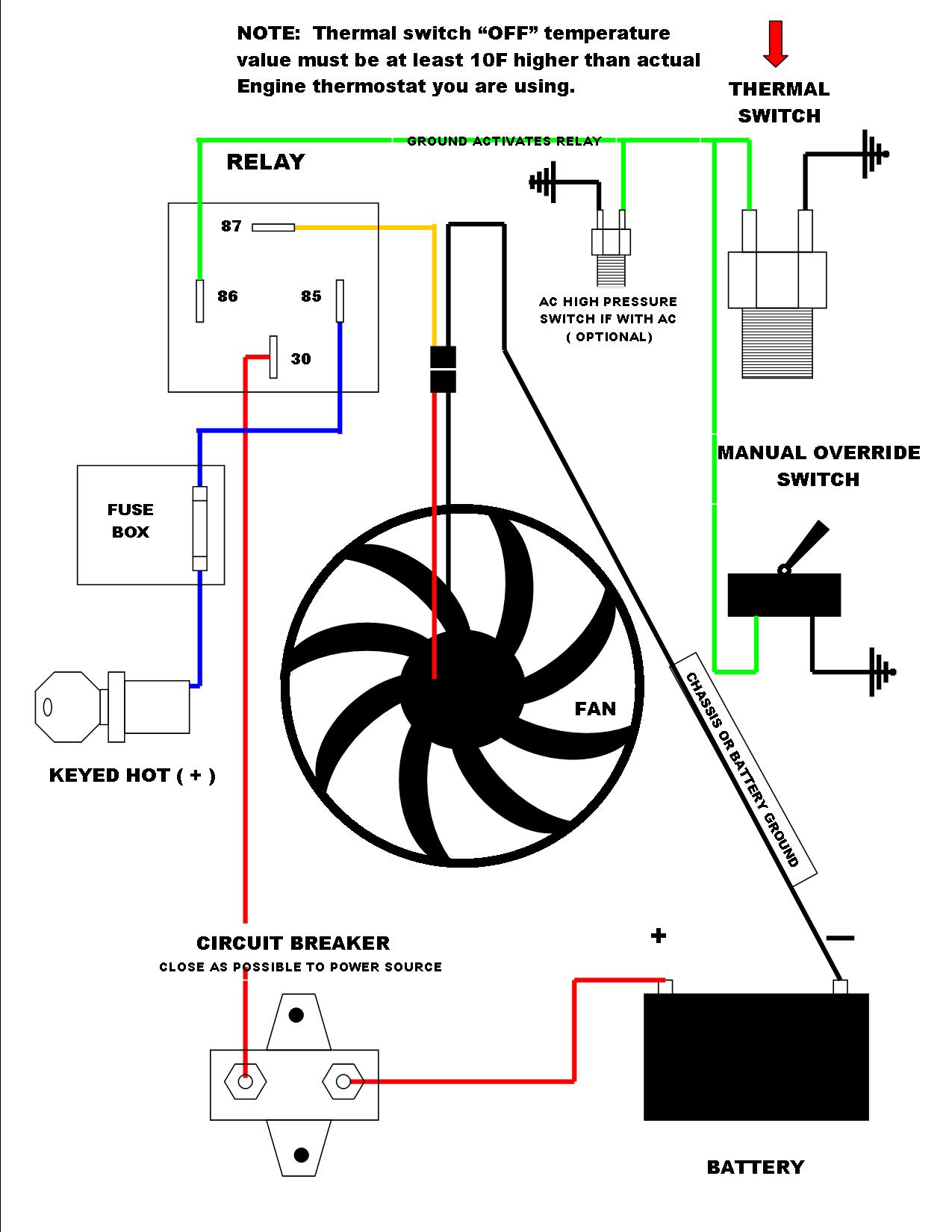
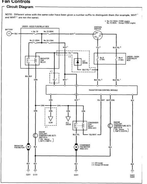
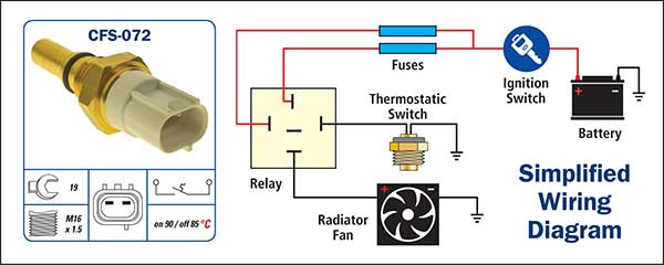
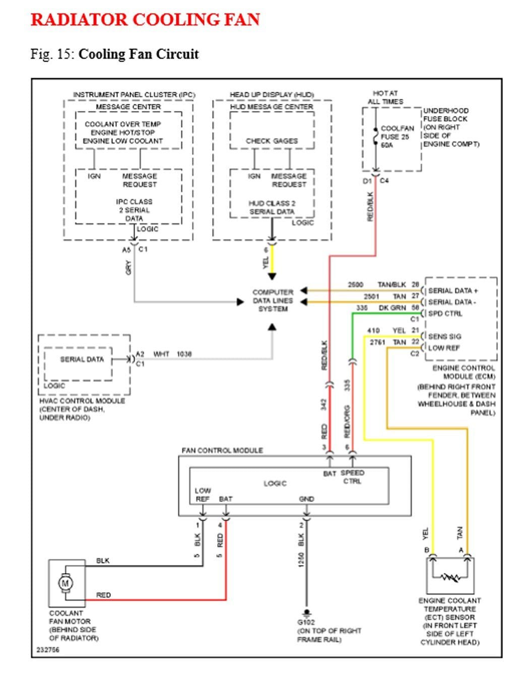
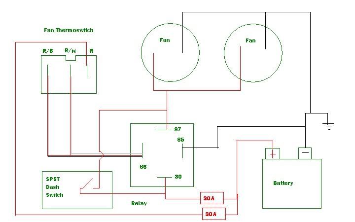
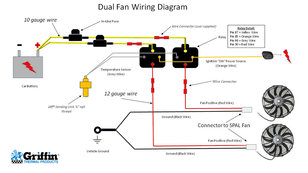
Cooling fan circuit diagram. Hi for the person that was looking to find the radiator fan control rely you have to. For smaller fans both fans can be connected to a single relay as shown above and the proper fuse should be installed to protect the circuit while at the same time providing enough current to flow without exceeding the fuse rating. Hayden flex a lite or perma cool brands can provide a 12 volt output when activated. Suggested electric fan wiring diagrams suggested primary cooling fan single speed onoff using 12 volt switching devices only for primary activation note. The override switch is not working. This is based on the draw from the fans if the fans are larger and draw more than 15 amps each its recommended to install a second relay kit as shown below.
It includes the following circuits. The block diagram includes power supply rst circuit 8051 microcontrollers lm35 temperature sensor 8 bit adc l293d motor driver dc motor 7 segment display ip switches. Relays shown in these diagrams can provide options for useful features such as an ac override on andor manual override on. The block diagram of the temperature controlled fan using a microcontroller is shown in the above figure. I have a basic diagram but doesnt explain what happens after the override switch if it grounds a module or powers a relay. Circuit diagram for fan speed control.
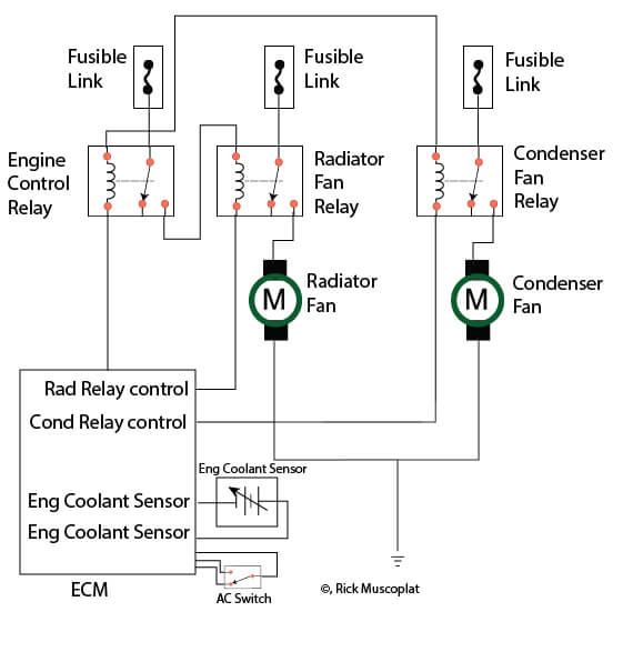
With dual cooling fans there are two methods for wiring up the relay kit. Radiator fan low speed radiator fan relay high speed radiator fan relay and engine coolant temperature sensor. The key component of this temperature controlled fan circuit is thermistor which has been used to detect the rise in temperature. The above radiator fan motor circuit diagram appliest only to the 2005 and 2006 24l dohc chrysler sebring and 24l dohc dodge stratus. Hi im looking for a good schematic and also circuit description for the engine cooling fan circuit including override switch. Below is the circuit diagram for temperature controlled dc fan using thermistor as temperature sensor.
Todays cooling fans are computer controlled and various. Image click to enlarge. Page 2 standard relay pins 30. Each one have 470ω resistance when the temperature increase this ntc gices low resistance. This circuit is designed to control small cooling fan speed of the fan is controlled by the ntc thermisters these kind of small fans are used to reduce the temperature of semiconductor devices by the varying temperature speed of fan varies automatically. The coolant temperature sensor feeds the computer the engine temperature.
There are two types of thermistor ntc negative temperature co efficient and ptc positive temperature co efficient we are using. Low speed fan relay circuit above these 2 relays is a hydraulic cooling fan module it is not a relay and only applies to 4. The computer decides whether only one fan is needed or 2 fans depending on engine temperature and ac load have your computer tested its jobs is to energize the appropriate relay as needed. Wiring dual cooling fans. Construction and working in this circuit power supply to the cooling fan given through four ntc thermisters. Thermistor is temperature sensitive resistor whose resistance changes according to the temperature.
Most stand alone adjustable thermostats ie. Constant 12v unswitched 85.
Gallery of Cooling Fan Circuit Diagram