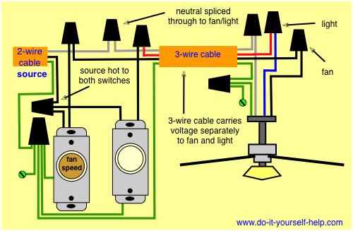
Ceiling fan switch wiring diagram 2 line voltage enters the switch outlet box and the line wire connects to each switch. Connects to switched lines and a neutral 3 wire cable that travels through the ceiling lights fan outlet buckles.

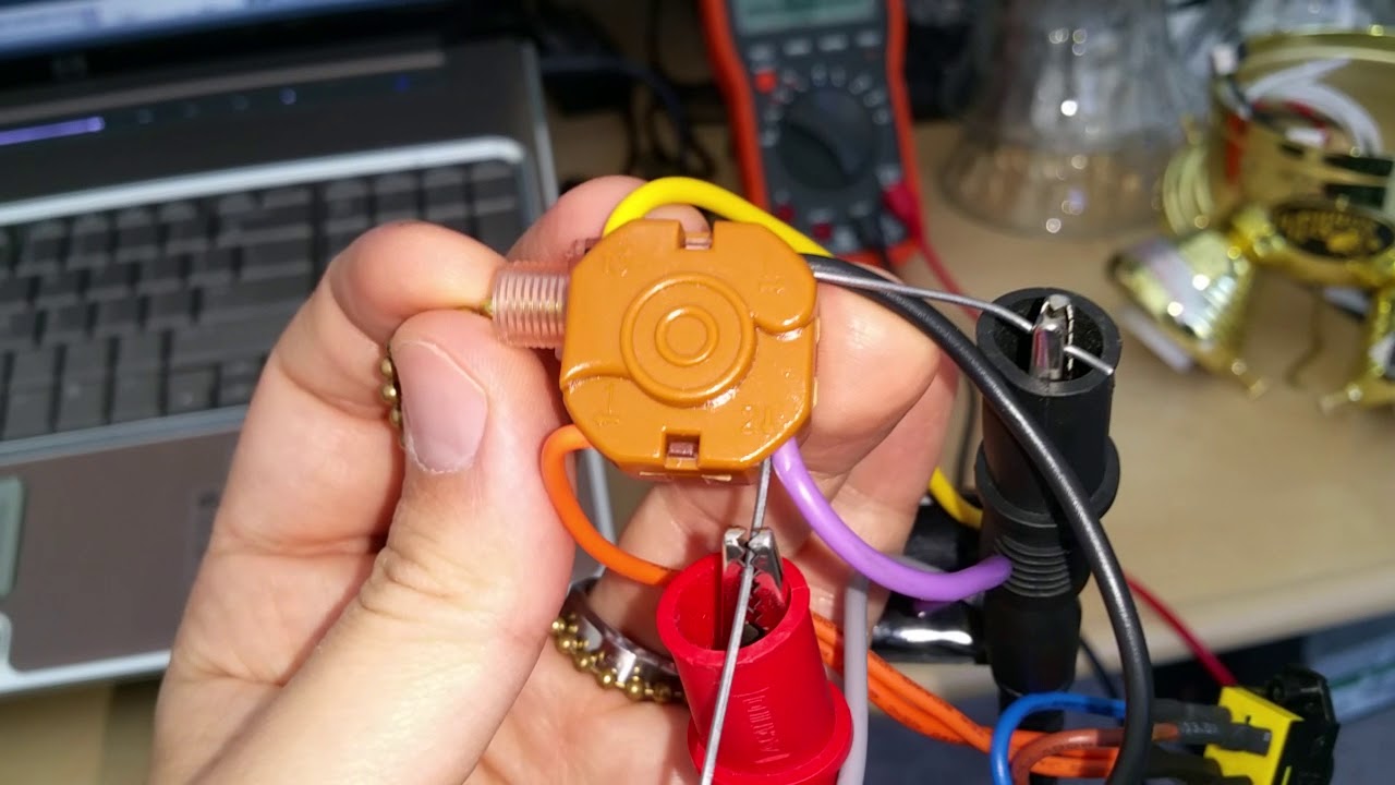
How To Wire 3 Speed Fan Switch
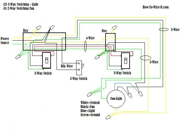
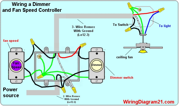
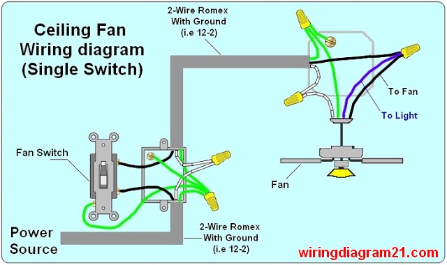
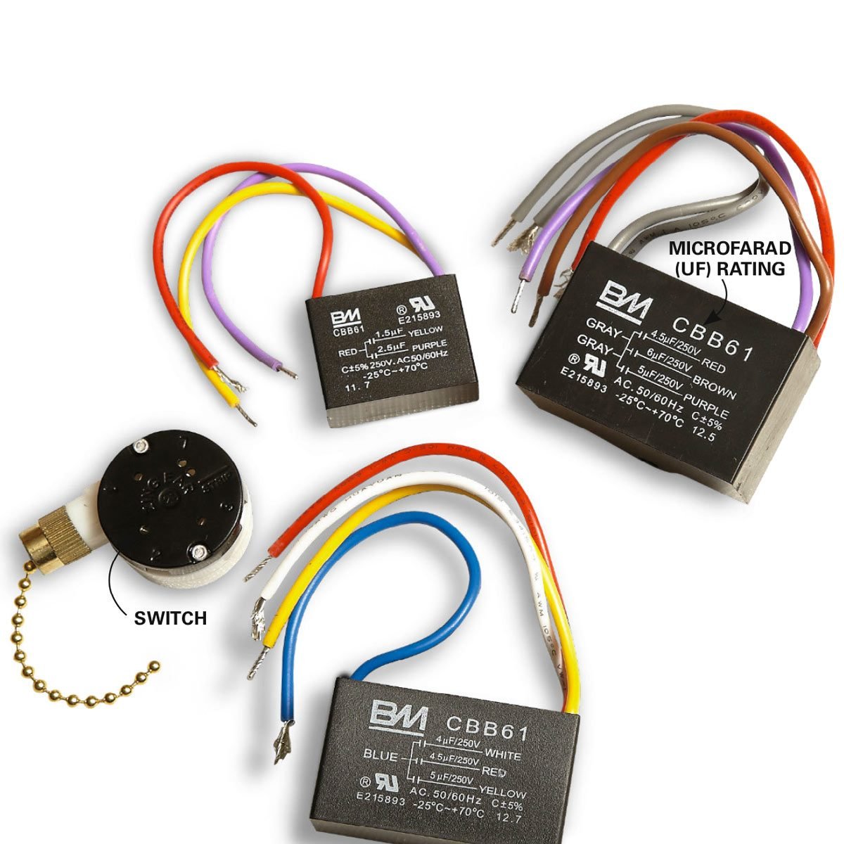
Ceiling fan switch wiring diagram. This wiring diagram illustrates the connections for a ceiling fan and light with two switches a speed controller for the fan and a dimmer for the lights. It reveals the elements of the circuit as simplified shapes and the power and signal connections between the tools. Black speed switch three wire capacitor. 1 to l and c1 2 3 slow. Connect the red wire to the screw in switch 2. Black speed switch with only three terminals connected two wire capacitor.
Collection of 4 wire ceiling fan switch wiring diagram. 1 to l c1 1 and c1 2. 1 to l and c1 1 2 med. Switched lines and neutral connect to a 3 wire cable that travels to the lightfan outlet box in the ceiling. The fan control switch usually connects to the black wire and the light kit switch to the red wire of the 3 way cable. Because the ceiling fan box is a junction box which supplies power to the wall plugs the wiring can be a little complicated and it would be best to.
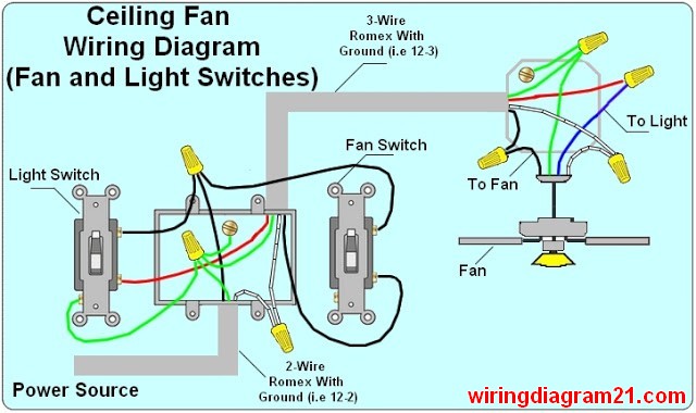
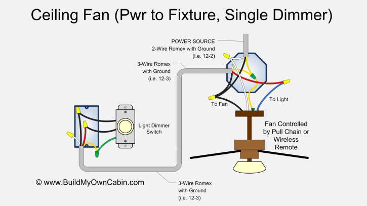
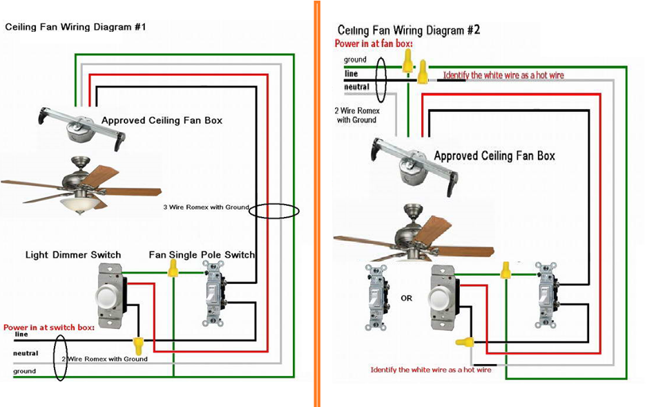
Ceiling fan and light switch wiring diagram. A wiring diagram is a streamlined standard pictorial depiction of an electrical circuit. Connect the black wire to the screw located in swith 1. The line voltage enters the switch outlet box and the hot wire will connect to every switch. Connect black fan wire to the black ceiling wire. Ceiling fan wiring diagram 1.
Speed switch connection table. Category number 3 4 speed 5 hole ceiling fan switch with black wire in terminal l and labeled l 1 2 3 4 counterclockwise zing ear ze 268s5 6a 125vac 3a 250vac. Switch hots and line neutral will connect to a 3 wire cable that travels to the fanlight outlet box in the ceiling. Connect white wires together. Speed switch connection table. The fan control switch is usually combined with a light kit switch with black wire and a 3 way cable red wire.
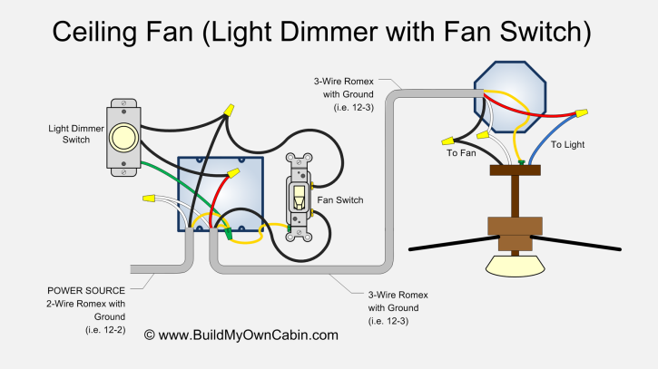
In this diagram the black wire for the ceiling fan is for the fan and the blue wire is for the light kit. Connect the blue wire to the red wire. The dimmer switch for the ceiling fan light is connected the same way as the regular switch which was wired at the wall switch box which will enable dimmer switch control for the ceiling fan light. Ceiling fan capacitor connection diagram 3 wire ceiling fan capacitor diagram 5 wire ceiling fan capacitor diagram and installation role of capacitor in fan and single phase motor so in above diagram the speed switch contacts on l 3 and 25 uf and fan on running or start on 25 micro farad cap and on med speed. The source is at the switches and the input of each is spliced to the black source wire with a wire nut. Split the incoming hot wire into a y and connect it to a terminal on each switch.
Ceiling fan wiring diagram 2. From the switches 3 wire cable runs to the ceiling outlet box. In the switch box.
Gallery of Ceiling Fan Switch Wiring Diagram