5 years agoceiling fan speed switch repairhunter fan speed control. Assortment of ceiling fan speed control wiring diagram.
Ceiling Fan Speed Switch Repair
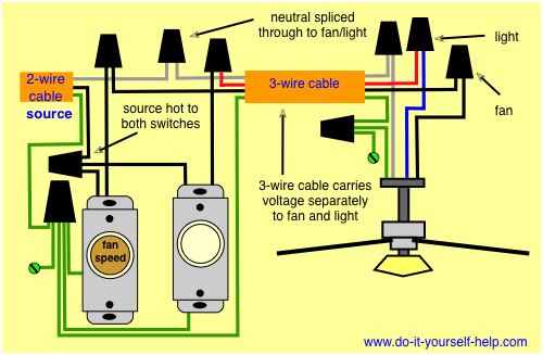
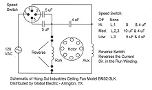
Ceiling fan speed control switch wiring diagram. Black speed switch three wire capacitor. Ceiling fan switch wiring diagram 2 line voltage enters the switch outlet box and the line wire connects to each switch. I need a wire diagram for a 3 speed 3 wire switch and diagram of capacitor for a model tfp ceiling fan my guess is the capacitor is connected wrong and that is why i am only getting 2 speeds submitted. Switched lines and neutral connect to a 3 wire cable that travels to the lightfan outlet box in the ceiling. 2 to 1 and 3 3 slow. Connects to switched lines and a neutral 3 wire cable that travels through the ceiling lights fan outlet buckles.
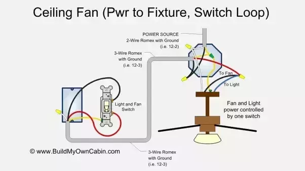
In the below ceiling fan speed control switch diagram i shown the fan speed switch knob on off direction. Ceiling fan wiring diagram 2. So yellow for 15 uf and purple for 25 uf. The fan control switch is usually combined with a light kit switch with black wire and a 3 way cable red wire. Ceiling fan speed control wiring diagram wiring diagram for dual switch ceiling fan new ceiling fan speed control switch wiring diagram. So here is an complete diagram in which is shown the ceiling fan motor main winding and auxiliary winding starting winding with speed controller switch capacitor and ac supply.
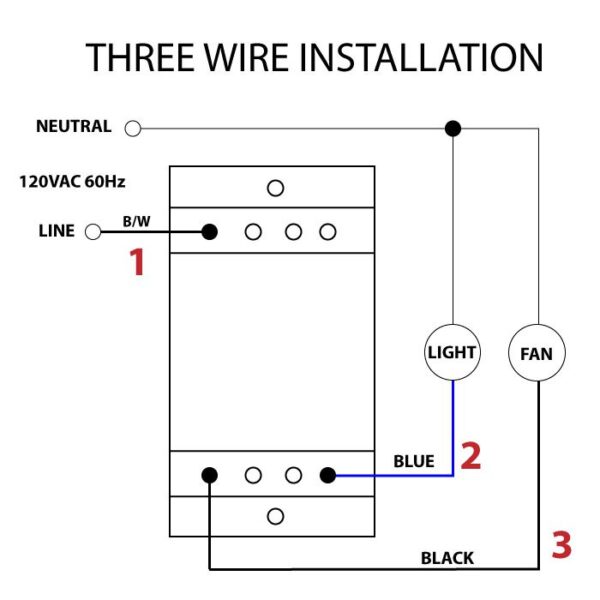
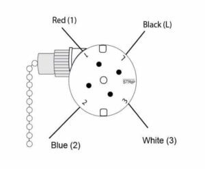
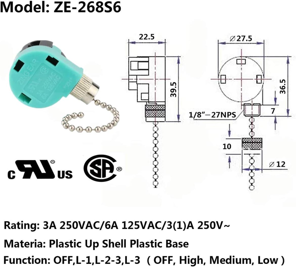
Ceiling fan wiring diagram 1. Black speed switch three wire capacitor. Speed switch connection table. 2 to 3 do not use an electronic speed control on this type. The fan control switch usually connects to the black wire and the light kit switch to the red wire of the 3 way cable. Black speed switch with only three terminals connected two wire capacitor.
Ceiling fan wiring diagram 1. 2 to 1 2 med. No connection 1 fast. In this diagram the black wire for the ceiling fan is for the fan and the blue wire is for the light kit.
Gallery of Ceiling Fan Speed Control Switch Wiring Diagram