An optional additional lamp can be connected at terminal a as a pilot lamp or to illuminate a long corridor. An optional receptacle can be connected at terminal b since that terminal is always live.

Coronavirus Instagram Founders Design Website To Track
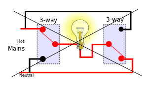
California 3 way diagram. Two very old three way switches. Below is a simple schematic diagram that can be applied to all three way electrical light switch connections. This is only a wiring schematic and not the actual wiring method used for 3 way switch installations. Two very old three way switches are depicted in the photo above. The california 3 way or coast 3 way connection never connects the lamp socket shell to the line hot terminal. Conventional 3 way wiring is not very complexwith conventional wiring the line line voltage connects to the common of one switch.
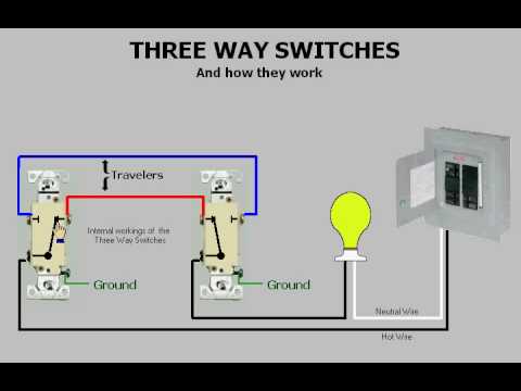
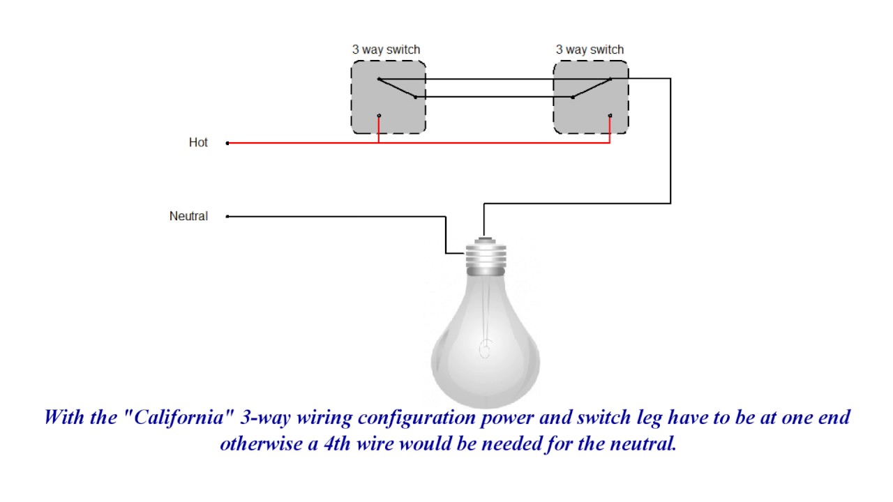
As you can see this picture corresponds to the diagram for the basic 3 way switch system above. Many variations of this basic theme are possible. All photos and diagrams may be copied for classroom instruction or personal use. For instance the 3 way switch schemes a b c above will allow a 4 way switch and box or any number of them to be interposed between the 3 way switch boxes. Best blog explaining 3 ways with wiring diagrams photos and 10 different 3 way switch wiring methods used in buildings throughout the us 120 volt. The alternate 3 way switch wiring configuration california or west coast was used as a way to wire 3 way switches and be able to supply line voltage to either switchthis configuration is no longer allowed as the neutral is not present in each switch box.
California three way switch wiring diagram wiring diagram is a simplified normal pictorial representation of an electrical circuitit shows the components of the circuit as simplified shapes and the skill and signal friends along with the devices. 3 way switch schematic wiring diagram.
Gallery of California 3 Way Diagram