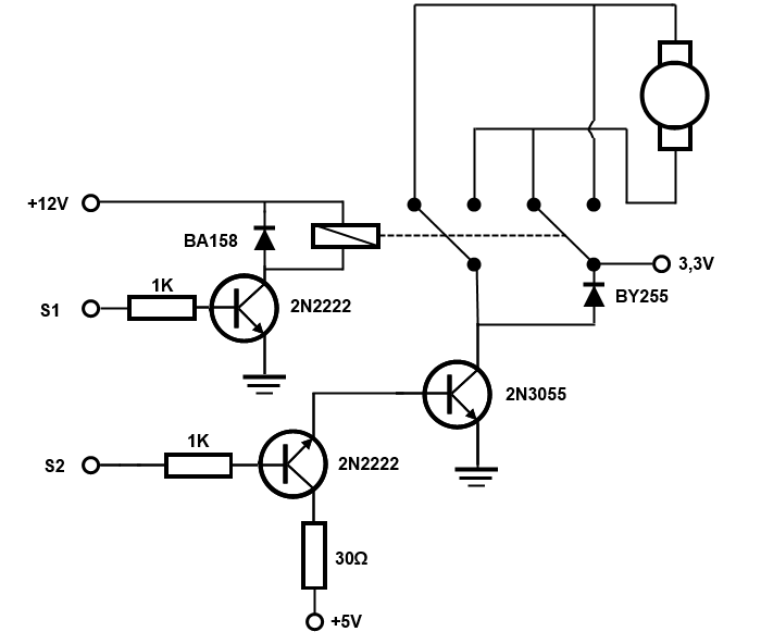
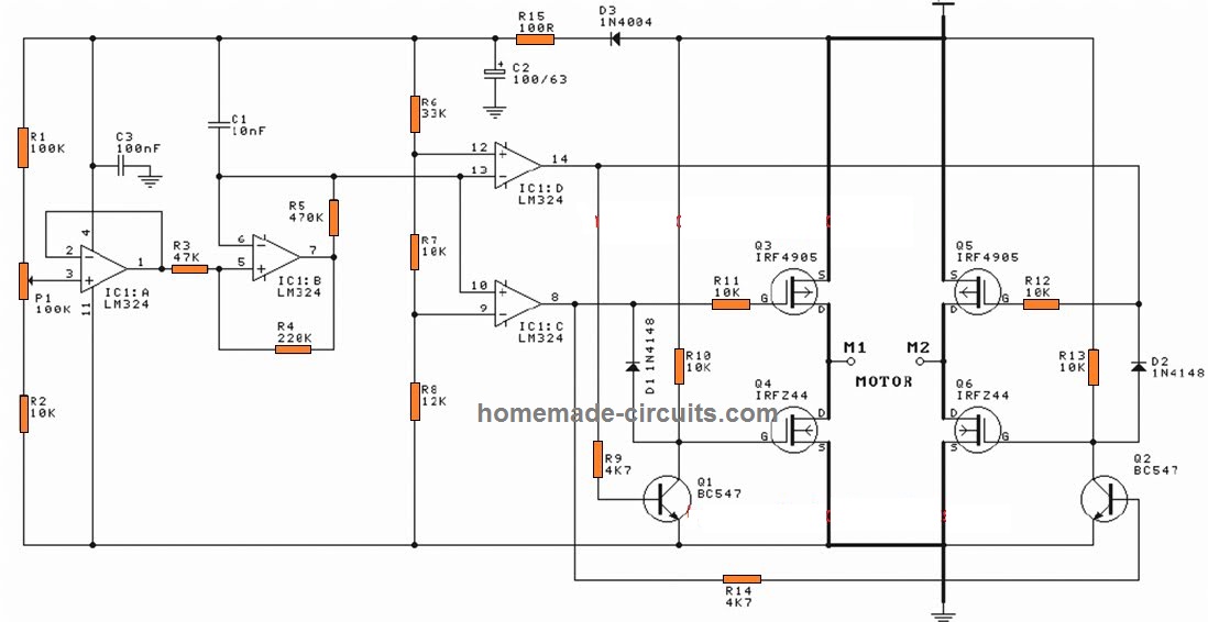
A circuit which allows a connected motor to operate in clockwise and anticlockwise directions through alternate input triggers is called a bidirectional controller circuit. The switch s1 and s2 control the relay 1 and relay 2 respectively.
Why Are You Still Driving Automotive Motors With Relays
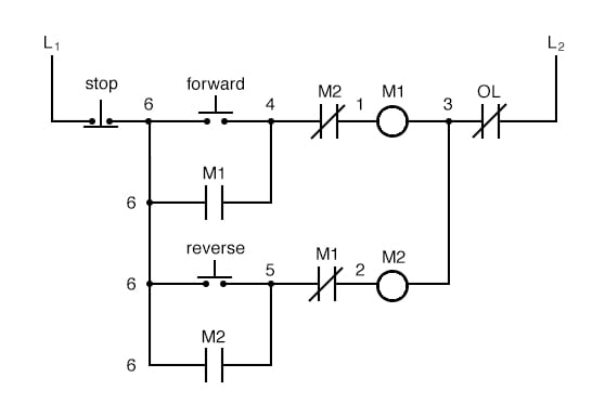
Bidirectional motor control using relay. The following circuit allows a motor such as a train to travel in the forward direction until it hits the up limit switch. The positive wire from the 9v battery will connect to both of the no top inputs. The coil terminals of the relay are connected to the supply with a push switch. Make the connections according to it. The backbenchers diy 3947 views. Circuit diagram of this bidirectional motor control project is shown in image below.
Connect normally closed terminal of both relays to positive terminal of battery. The circuit operation is straight forward. How to make dc motor forward reverse control using relay diy project the backbenchers diy duration. Output of an astable mutivibrator based on ic1 ne555 is used to control the relay rl1 driving the motor. This sends a pulse to the latching relay to reverse the motor and ends the short pulse. It operates on 12 volts and the ba158 diode protects the transistor against the return currents that can occur when the coil is depolarized.
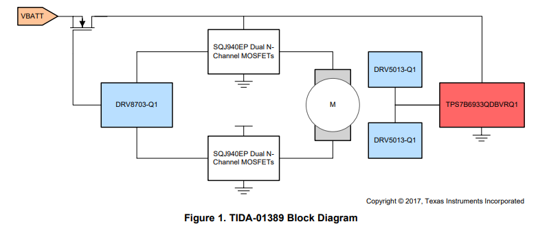
The relay which switches the two circuits is controlled by a 2n2222 npn transistor which is activated or deactivated by one of the digital outputs from the arduino board. The train travels to the down limit switch and reverses. In this project both wires from the motor will connect to both of the com middle inputs of the relay switches. Connect normally open terminal of both relay to drain terminal of mosfet. In the circuit diagram shown the switch s1 is on and switch s2 is off. This input is perceived by the motor as an intermediate voltage and not as a stream of onoff voltage.
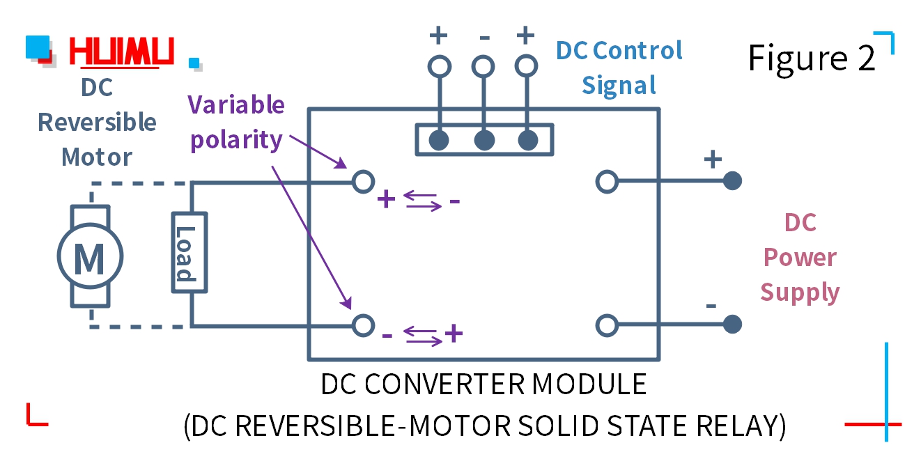
The negative wire from the 9v battery will connect to both of the nc bottom inputs. This is a simple and easy to construct circuit that can be used to provide a bidirectional drive to a dc motor. So the motor terminals will have a positive polarity on the left side and a negative polarity at the right side. The motor is connected between the two poles of the relay contacts. The trasnsitor based h bridge can control the motor speed using the pwm technic which is nothing more than a fast flickering of the transistors.
Gallery of Bidirectional Motor Control Using Relay