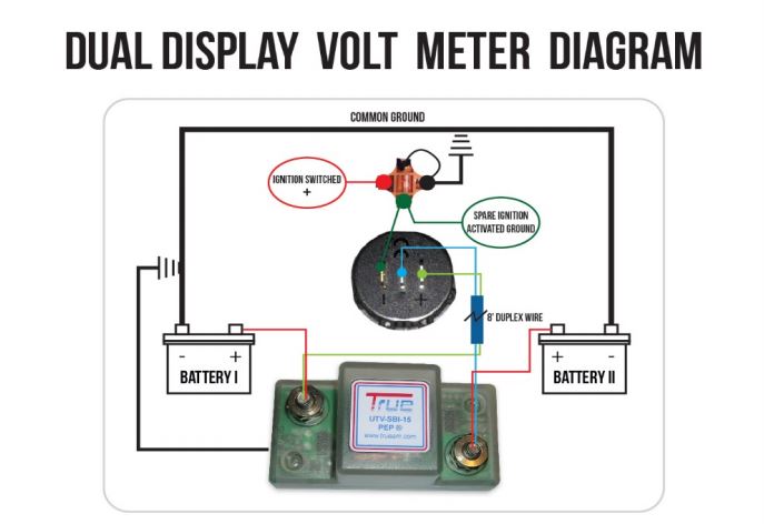
Use 18 awg wire. This is not an ideal way to fully charge.

Cg 7472 Battery Isolator Wiring Diagram Battery Switch
Battery isolator wiring diagram manufacturers. You can charge the auxiliary battery with a battery charger without affecting the battery isolator at any time. Typical battery isolator circuits arco the most common battery isolator is the one alternator two battery unit. After answering numerous questions about different battery isolator schemes i decided it would be easier to just build a webpage. Battery isolator wiring diagram manufacturers architectural circuitry diagrams show the approximate locations and interconnections of receptacles lights and irreversible electric solutions in a building. It shows the parts of the circuit as streamlined forms and the power as well as signal connections between the tools. Wiring diagram battery isolator controller part no 00 00131 000 by intellitec aux.
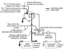
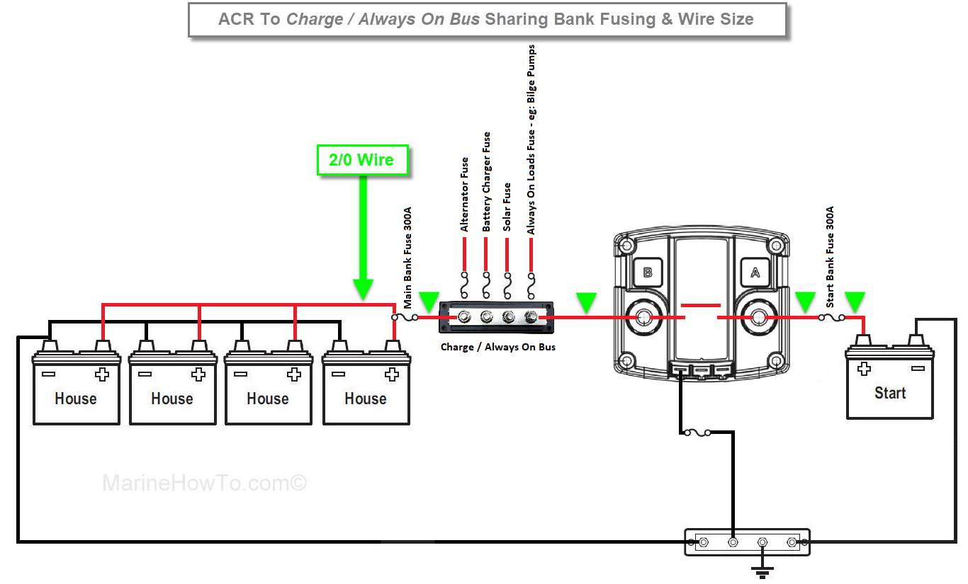
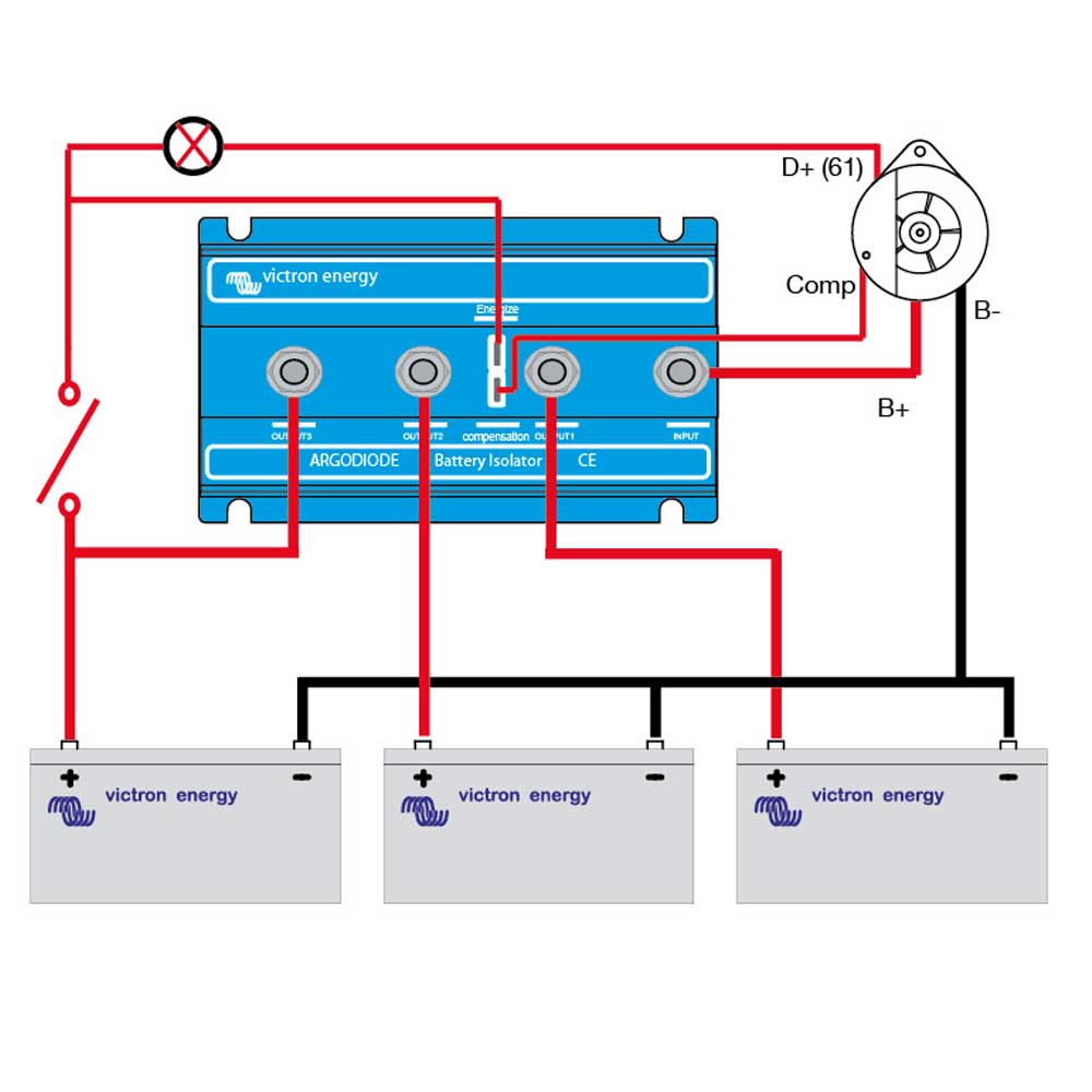
For your battery isolator similar to dw08771 you will have connection posts for each battery and for an alternatorthe main battery will connect to position one and the alternator to the a post. The second battery will attach to the 2 via a circuit breaker that is rated appropriately for the battery. Connect a new 10 gauge wire from the b3 terminal of the isolator to the new auxiliary battery positive. Below you will find the basic design of 3 types of battery isolators with the pros and cons of each. It consists of instructions and diagrams for different types of wiring methods along with other items like lights windows etc. Setup a digital multi meter dmm in the diode test mode.
Connect a new 10 gauge wire from the b1 terminal of the isolator to the existing 1 main battery positive post. An alternative indicator lamp could be connected in parallel with the relay coil. Dual battery isolator schematic. Remove all wire connections from the isolator. Start light normal start light to chassis 12v to starter relay coil to coach battery to chassis ignition to ground to isolator relay coil note. Diagram 4 alternator to battery isolator with r kit and additional battery auxiliary battery used on model 2504 auxiliary battery alternator 70a max r r kit guest pn u 3059 main battery battery isolator testing 1.
Interconnecting cable routes might be revealed around where particular receptacles or fixtures have to be on an usual circuit. Connect a new 10 gauge wire from the b2 terminal of the isolator to the existing 2 main battery positive post. When charging the starting battery the isolator will automatically connect the auxiliary battery when the starting battery reaches 134v about 75 charged and will then be charged also. It doesnt matter how many batteries are connected in parallel to the battery 1 or 2 terminal. Collection of battery isolator wiring diagram manufacturers. A wiring diagram is a simplified standard photographic representation of an electric circuit.
Cole hersee battery isolator wiring diagram schematic diagram dual battery isolator wiring diagram wiring diagram consists of several detailed illustrations that present the connection of varied products.
Gallery of Battery Isolator Wiring Diagram Manufacturers