Contact us and let us know what is on your mind. A 4 way switch must be wired between two 3 way switches as shown in the diagrams on this page.
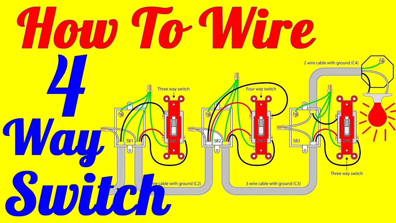
4 Way Light Switch Wiring Diagram How To Install
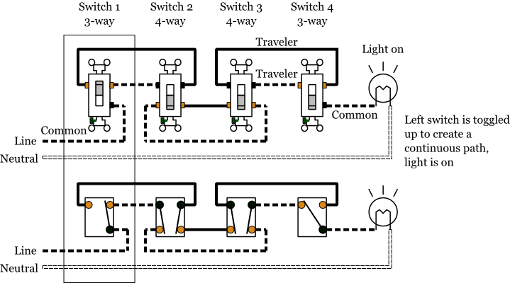
4 way wiring diagram. Two wire cable is run from the light to sw1 and 3 wire cable runs between the three switches. If you understand how to wire a 3 way switch youll have no issues with a 4 way switch. Trailer wiring diagrams 4 way systems 4 way flat molded connectors allow basic hookup for three lighting functions. One ground and 4 circuit terminals divided into two matching pairs called travelers. You can have an indefinite number of 4 way switches in a circuit. A 4 way switch has five terminals.
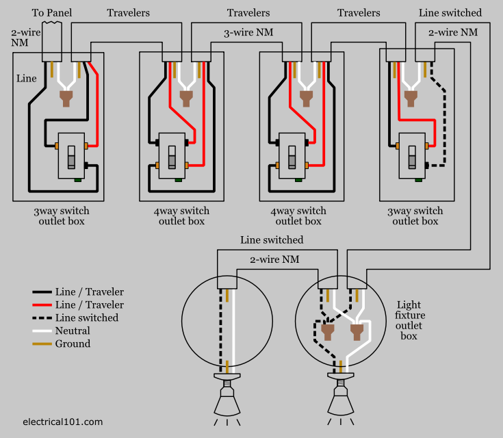
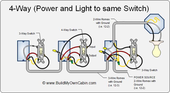
Basic 4 way switch wiring diagram. The electrical switch box that contains the line and load wires may need to be bigger than the other switch boxes especially if there are other wires going into the switch box. This diagram illustrates wiring for a 4 way circuit with the electrical source at the light fixture and the switches coming after. Below is another method for wiring 4 way switches. When wiring in the 4 way switch it is most simply described as simply cutting the two traveler wires the two wires that go between the two 3 way switches and terminate on each switch and putting two wires from one switch on the top two terminals of the 4 way switch while putting the other two wires from the other switch on the bottom two terminals. 4 way switch wiring with light first.
Click here to access. More 4 way switch wiring diagrams four way switch wiring schematic. For complete instructions on wiring a basic 4 way switch see our wiring a 4 way switch article. They all must be between the two 3 way switches. The black line wire connects to the common terminal of the first 3 way switch. How to wire a split receptacle.
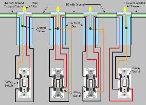
Watch the 4 way switch video below and pay attention. Typical 4 way switch wiring nm cable in the 1st diagram below a 2 wire nm cable supplies power from the panel to the first switch box. A 3 wire nm connects the traveler terminals of the first 3 way switch and the first 4 way switch. This diagram is a thumbnail. 4 way switch wring diagram. 4 way tow vehicle side.
In general practice the diagram above is most often used and is a good guide for wiring a new 4 way switch circuit. 4 way switch wiring diagrams this 4 way switch diagram 1 shows the power source starting at the left 3 way switch. The white wire of the cable going to the switch is attached to the black line in the fixture box using a wirenut. The 4 way is used when you want to control the light or lights from two or more locations. Right turn signal stop light green left turn signal stop light yellow taillight license side marker brown and a ground white. Each pair of traveler terminals should be wired to the traveler wires from one of the 3 way switches in the circuit.
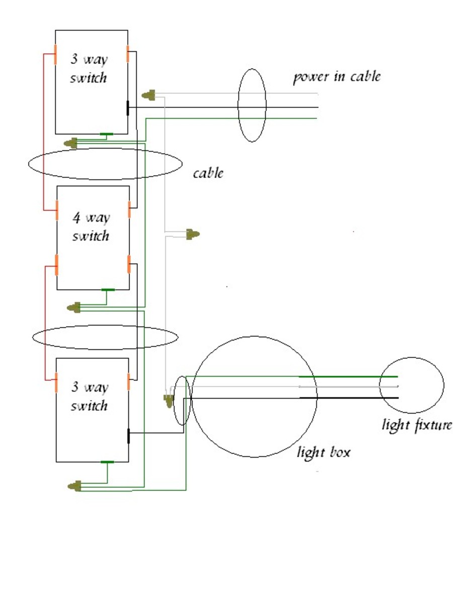
A 4 way switch is always placed in between two 3 way switches. This 4 way switch diagram 2 shows the power source starting at the fixture.
Gallery of 4 Way Wiring Diagram