The wire stripper will work on both solid and stranded wire. The diagram below will give you a good understanding how this circuit is wired.
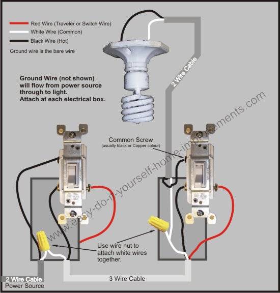
Wiring A 3 Way Switch
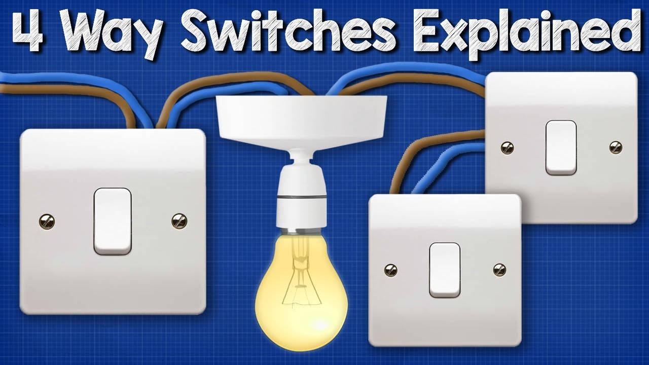
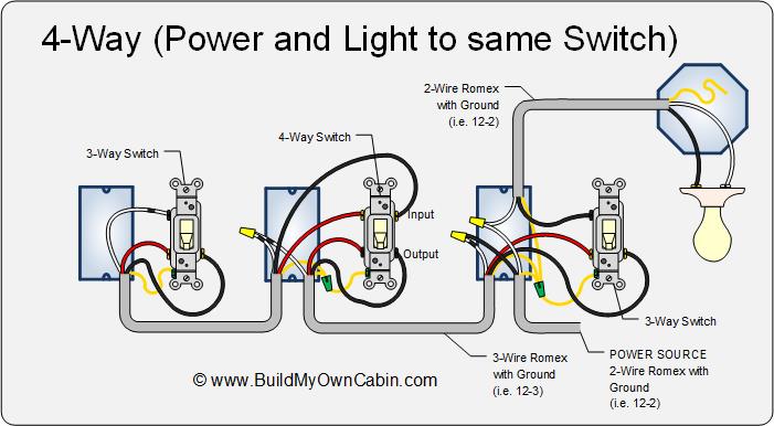
4 way switch internal diagram. Follow the switch manufacturers instructions and wiring diagram as the connections on the switch vary by manufacturer. Start here for practical circuits with different arrangments of switches and lights including proper color codes. For complete instructions on wiring a basic 4 way switch see our wiring a 4 way switch article. They all must be between the two 3 way switches. My 4 way switches dont work. A similar page for 3 way switch circuits.
A 4 way switch wiring diagram is the clearest and easiest way to wire that pesky 4 way switch. The end of the tool can be used to grip and bend wire which is handy for attaching wire onto the screw terminals of switches and outlets. Conventional 4 way switch wiring. Each pair of traveler terminals should be wired to the traveler wires from one of the 3 way switches in the circuit. To view it at full size click on the diagram. A 4 way switch has five terminals.
My 3 way switches dont work. This 4 way switch diagram 2 shows the power source starting at the fixture. The red and black wires are connected to the four way switches. Also this example is just adding a single 4 way switch which will give you 3 locations to control your light. 4 way switch wring diagram. Click here to access note.
I have a few of the most common ways in wiring a 4 way switch to help you with your basic home wiring projects. Sometimes the switch wiring connection diagram is printed on the inside of the 4 way switch packaging box see example below. Use this if you began repairing and replacing a 4 way switch circuit and ran into problems. In the diagrams below the first switch 3 way common terminal connects to. If you understand how to wire a 3 way switch youll have no issues with a 4 way switch. The wire gauges are shown on the side of the tool so you know which slot to use for stripping insulation.
The 4 way is used when you want to control the light or lights from two or more locations. This diagram is a thumbnail. Back to 3 way and 4 way light switches. A 4 way switch is always placed in between two 3 way switches. You can have an indefinite number of 4 way switches in a circuit. One ground and 4 circuit terminals divided into two matching pairs called travelers.
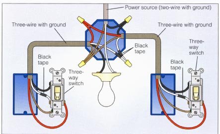
The white wire of the cable going to the switch is attached to the black line in the fixture box using a wirenut. A four switch configuration will have two 3 way switches one on each end and two 4 way switches in the middle. A 4 way switch must be wired between two 3 way switches as shown in the diagrams on this page. 4 way switches have four terminals each with two pairs of travelers one set usually black and one set usually brass color. Watch the 4 way switch video below and pay attention. This 4 way switch diagram 1 shows the power source starting at the left 3 way switch.
To add more locations to this circuit you just simply add additional 4 way switches in series with the existing 4 way switch.
Gallery of 4 Way Switch Internal Diagram