Pick the diagram that is most like the scenario you are in and see if you can wire your switch. Watch the 4 way switch video below and pay attention.

Three Switch Wiring Diagram 4 Wires H1 Wiring Diagram
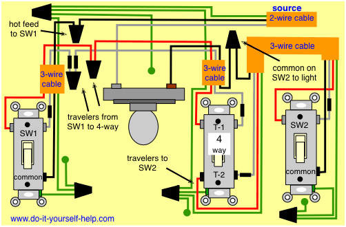
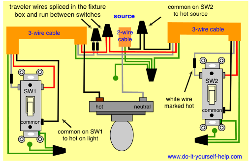
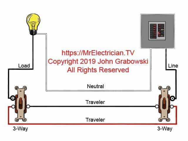
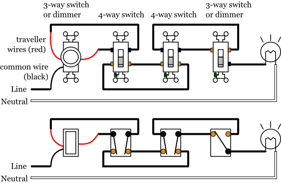
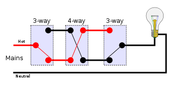
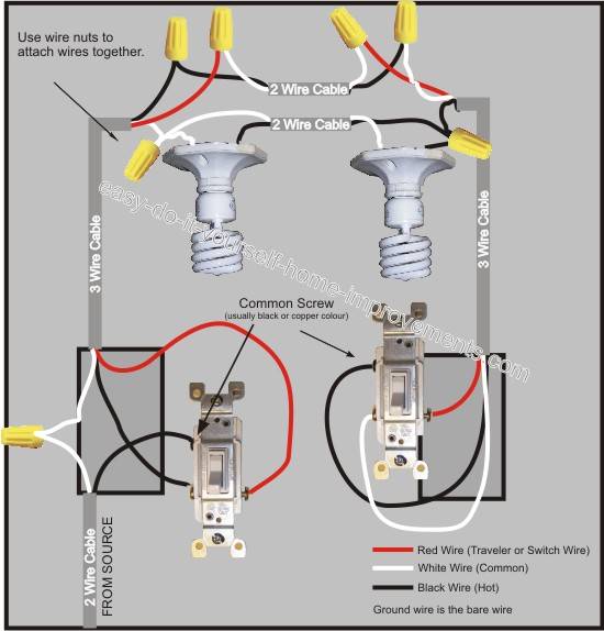
3 way switch with 4 wires. Two 3 way switches are connected to each other via traveler wires only one of which is hot in any given switch setting combination. Find the wires connected to the two traveler terminals. The white wire must be re identified as a hot wire at each switch location. One ground and 4 circuit terminals divided into two matching pairs called travelers. If you understand how to wire a 3 way switch youll have no issues with a 4 way switch. 3 and 4 way switches are used to control one or more lights or fixtures from 2 or 3 switch locations such as the top and bottom of a flight of stairs.
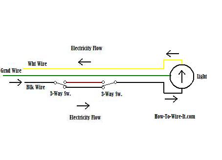
Take a closer look at a 3 way switch wiring diagram. Wiring a three way dimmer switch uses four wires and allows you the convenience of dimming the light from separate switches at opposite ends of a room. A 4 way switch must be wired between two 3 way switches as shown in the diagrams on this page. Each 3 way switch has a common terminal and two traveler terminals. The white wire between switches is not being used as a neutral. This might seem intimidating but it does not have to be.
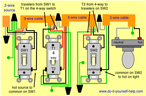
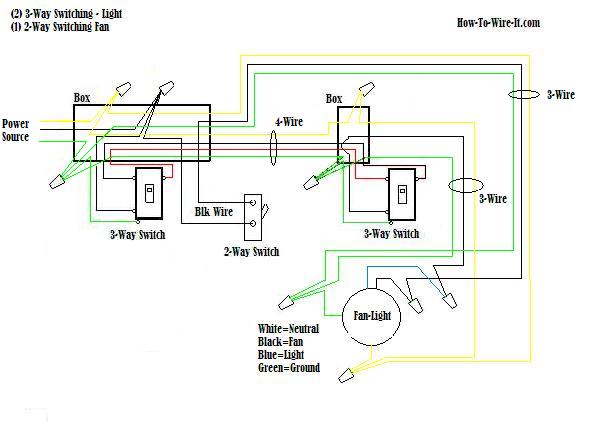
The 4 way switch connects in the middle of the two travelers. 3 way switch wiring diagram with line and load in the same switch box. An example of three way switch wiring with the line and load in the same 4 square electrical box. A 4 way switch is always placed in between two 3 way switches. Turn off the power at the circuit breaker. Each pair of traveler terminals should be wired to the traveler wires from one of the 3 way switches in the circuit.
Phillips or slotted screwdriver. A 4 way switch has five terminals. They all must be between the two 3 way switches. You can have an indefinite number of 4 way switches in a circuit. With these diagrams below it will take the guess work out of wiring.
Gallery of 3 Way Switch With 4 Wires