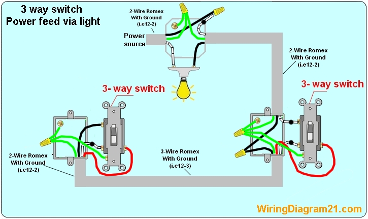
When nothing is hooked up there is power in the 2 wire plus ground cable on the upstairs switch. Regardless of what 3 way switch wiring diagram youre following youll need to use a 3 wire cable to connect the two 3 way light switches.
Is This An Acceptable Way To Wire A 3 Way Switch Circuit With
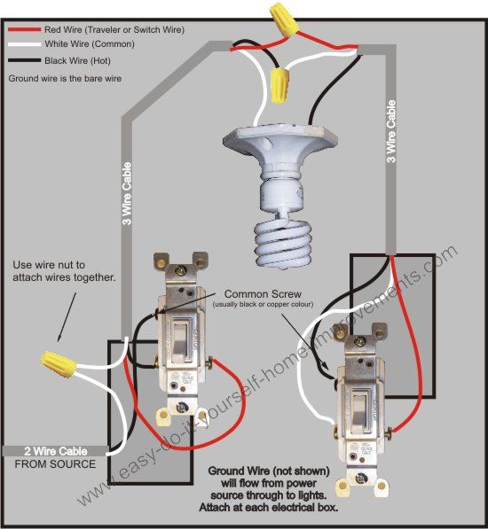
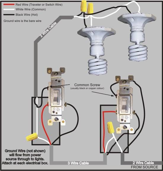
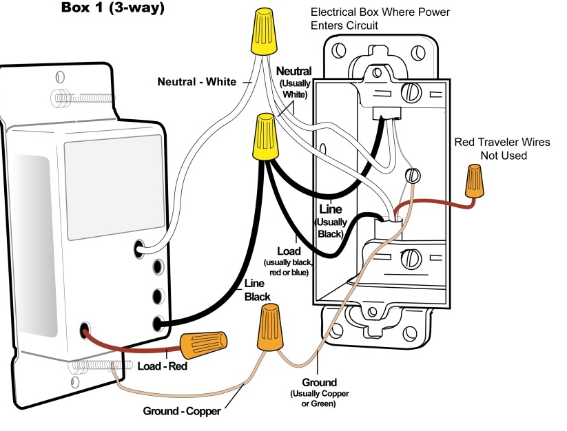
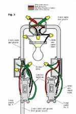
3 way switch wiring power at switch. This 3 way switch wiring diagram shows how to wire the switches and the light when the power is coming to the light switch. The black line wire connects to the common terminal of the first 3 way switch. Each 3 way switch in these examples are controlling the power source to the same load. Typical 3 way switch wiring nm cable. This terminal is usually identified by a darker colored screw. The key to wiring 3 way switches the power feed and the switch leg leading to the fixture s typically one at each switch location are attached to the screw terminal found at one end of the switch by itself.
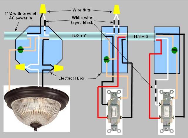
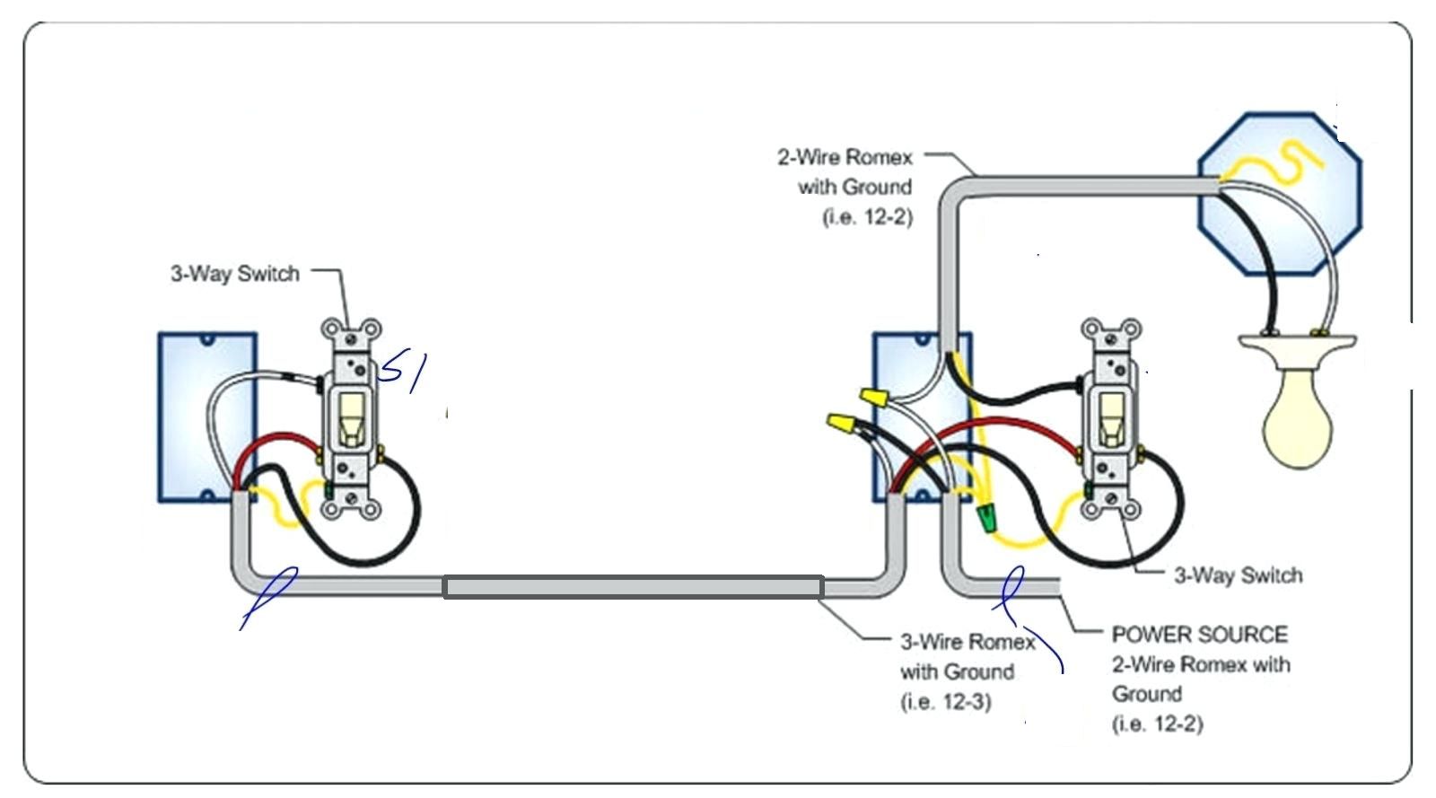
There is only the single 3 wire plus ground in the downstairs switch box and only two 2 wire plus ground cables at the fixture. Traveler wires are interchangeable on each switch. In this diagram the incoming hot wire attaches to the first switchs common dark colored terminal. Then a 4 wire cable going between the two 3 way switches and then a 3 wire cable going from the switches to the load. When wiring a 3 way switch circuit we will be using a 3 wire cable known as romex coming from the source such as the breaker box. A 3 wire nm connects the traveler terminals of the first and second 3 way switch together.
So what you should see if you have correct 3 wire electrical cable romex is a black power white neutral and now a 3rd red wire. The two hot wires of three wire cable connect to a pair of brass colored traveler terminals on each switch. In the 1st diagram below a 2 wire nm cable supplies power from the panel to the first switch box. The two switches appear to be connected by a 3 wire plus ground cable.
Gallery of 3 Way Switch Wiring Power At Switch