Something was wrong with the solid state circuitry everything worked but the motor but a quick test of the motor indicated it does work. Dec 28 generic 3 speed reversible spinner wiring diagram.
Btu Buddy 144 Fan Motor Problem For A Gas Furnace 2015 03
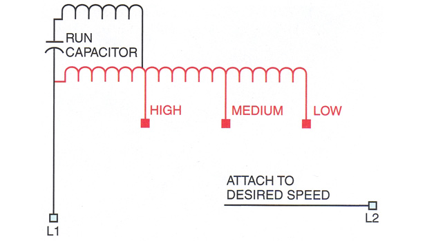
3 speed fan motor wiring diagram. The load will slow the motor down. However it does not imply link between the wires. According to earlier the traces in a hampton bay 3 speed ceiling fan switch wiring diagram represents wires. The motor will also have three speed wires and one neutral wire. Collection of hunter 3 speed fan switch wiring diagram. Using the fan manufacturers wiring diagrams as a guide locate the wires for the three speed switch and the fans motor.
It reveals the elements of the circuit as streamlined forms and the power as well as signal links between the tools. In addition wiring diagram gives you time frame by which the assignments are to be accomplished. However in sha allah in further post i will explain the fan 5 wire capacitor regulating speed switch diagram and replacement of fan capacitor in fan motor. It has a 3 speed fan motor. I have a bionaire brand table electric fan. If all that is correct the diagram below would be the complete connection diagram.
A wiring diagram is a simplified traditional pictorial representation of an electrical circuit. Sometimes the wires will cross. There are 6 wires. Inspirational 3 speed fan motor wiring diagram ac how to wire 1 3 speed fan wiring diagram. Collection of westinghouse 3 speed fan switch wiring diagram. How to wire 3 speed fan switch 3 speed fan wiring diagram.
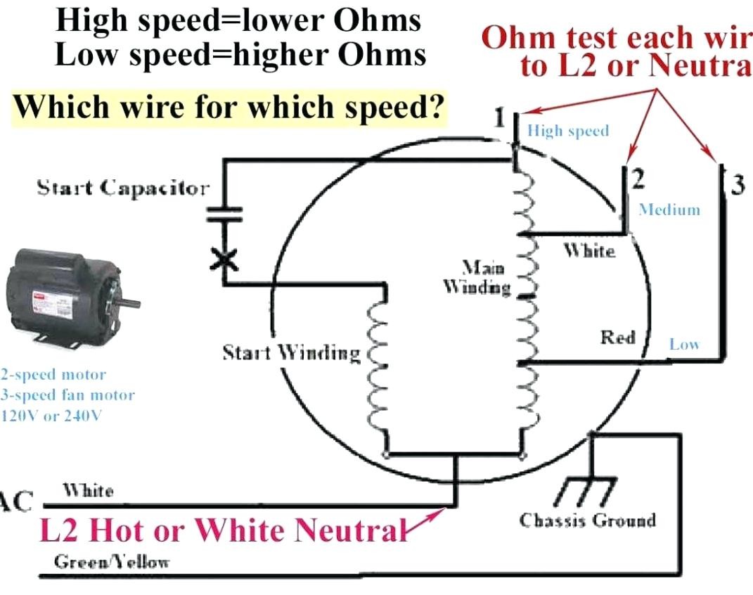
This is the schematic from the manual of the fan which i salvage this motor from. This fan has an oscillating grill with independent sync motor and timer circuit. White wire has a high speed label. Wiring diagram also provides beneficial suggestions for tasks that may demand. The switch will have a single main input wire known as the line and three additional wires that control speed. I have no knowledge about motors.
With the motor disconnected from the load the speed will be close to 1500 rpm regardless of the connection. The motor uses. 3 high speed green brown diagram ic1 3ø wiring diagrams 1ø wiring diagrams diagram er9 m 3 1 5 9 3 7 11 low speed high speed u1 v1 w1 w2 u2 v2 tk tk thermal overloads two speed stardelta motor switch m 3 0 10v 20v 415v ac 4 20ma outp uts diagram ic2 m 1 240v ac 0 10v outp ut diagram ic3 m 1 0 10v 4 20ma 240v ac outp uts these diagrams. It shows the parts of the circuit as simplified forms and the power and signal links between the gadgets. Yellow has a medium speed label and blue has a low speed label. Injunction of 2 wires is generally indicated by black dot at the intersection of two lines.
Youll be able to know exactly when the assignments ought to be accomplished that makes it much easier to suit your needs to effectively manage your time. One more thing to keep in mind is that the actual operating speed for a motor like this is determined by the load. The motor has a 4mu 250volt capacitor. As i shown in the above ceiling an 3 wire capacitor diagram that red is common wire and yellow for microfarad and purple for farad. The electric motor is a bm 122 decomin brand 3 speed motor. There are 4 wires connected to the motor coloured white yellow blue and black respectively.
A wiring diagram is a simplified standard pictorial representation of an electric circuit. Hope someone can enlighten me on the.
Gallery of 3 Speed Fan Motor Wiring Diagram