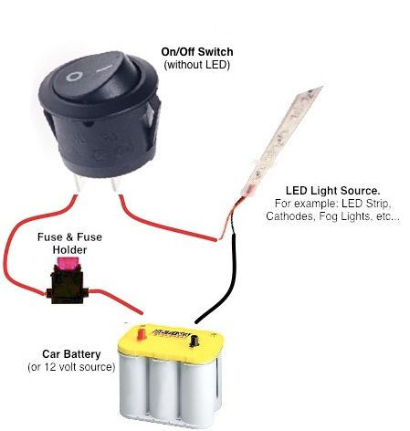
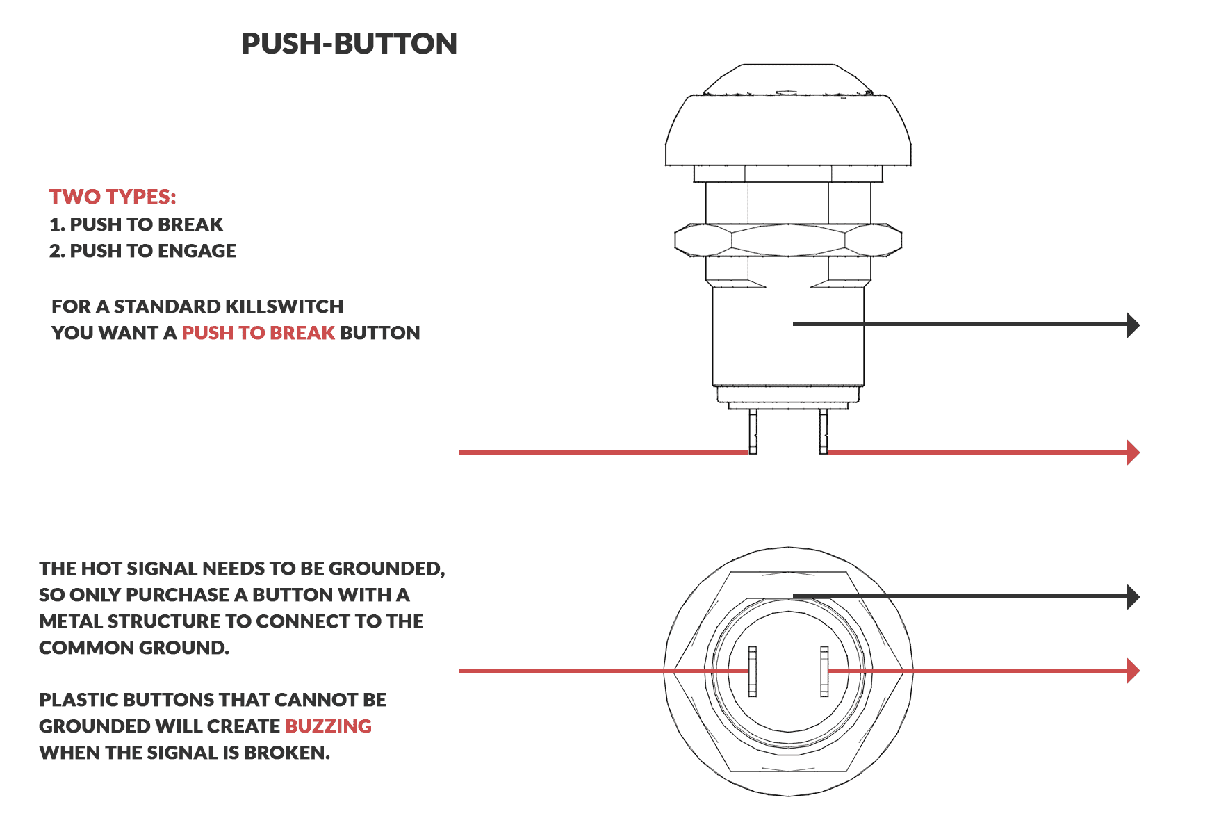
Examples of momentary switches push button. We will now go over the wiring diagram of a dpdt toggle switch.
How To Wire 4 Pin Led Switch 4 Pin Led Switch Wiring
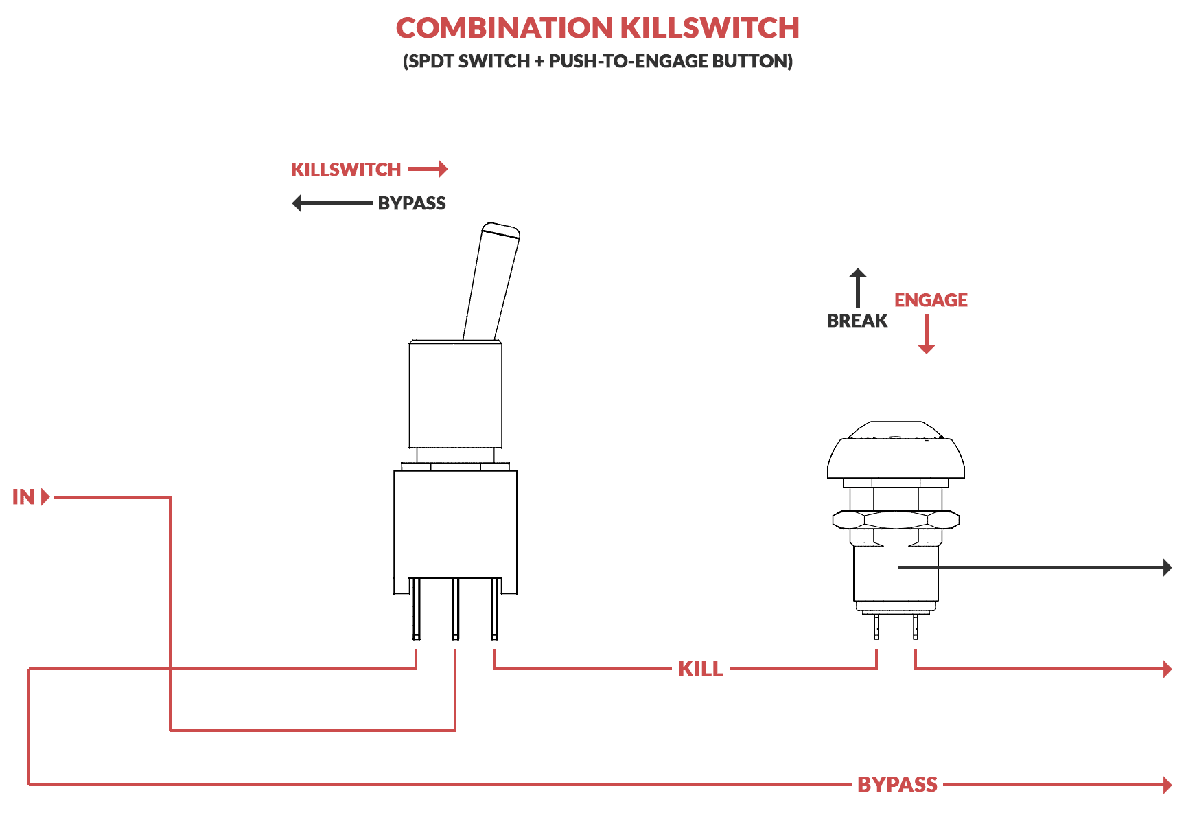
3 pin momentary switch wiring diagram. A dpdt toggle switch has 6 terminals. Below is the schematic diagram of the wiring for connecting a dpdt toggle switch. These terminals receive the power necessary to drive the loads on terminals 1 and 5 and 2 and 6. Stuff like reset or keypad buttons. Push button switches are the classic momentary. Momentary switches are switches which only remain in their on state as long as theyre being actuated pressed held magnetized etc.
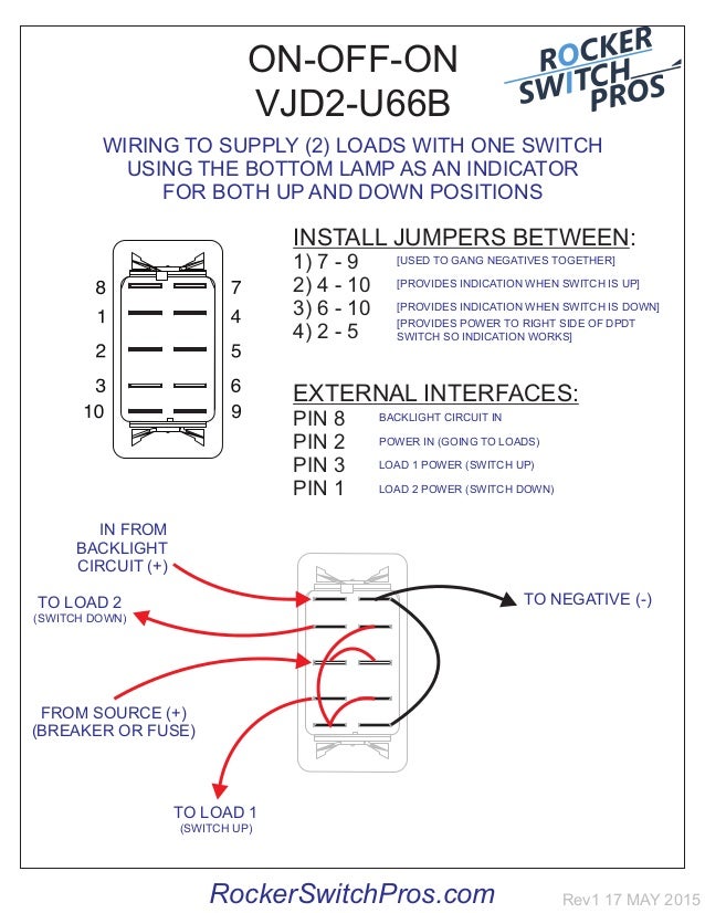
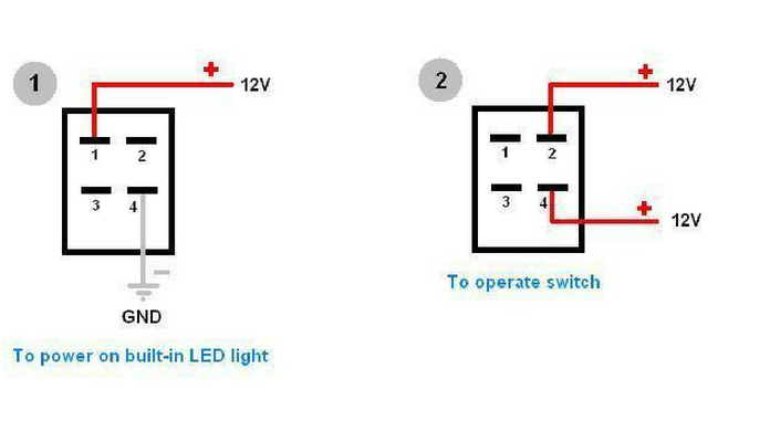
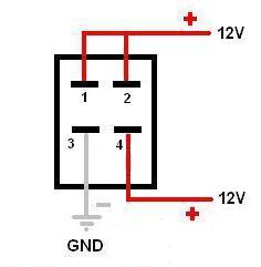
Pin 1 is where the rocker switch receives the input power. Terminals 3 and 4 represent the toggle switch. Pin 6 sync is responsible for sync and mode input. Below is a pictorial representation of the schematic diagram. Pin 3 is where the switch is either connected to ground or left open. This rocker is perfect for an engine offrunstart switch.
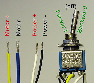
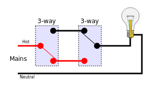
Pin 5 2 are taking vdd vss power supply and pin 1 gives output during the touch occurs. Quentacy 19mm 3 4 metal latching pushbutton switch 12v buy quentacy 19mm 3 4 metal latching pushbutton switch 12v power symbol led 1no1nc spdt on off black waterproof toggle switch with wire socket plug blue how to wire a 3 way switch wiring diagram how to wire 3 way light switches with wiring diagrams for different methods of installing the wire. To convert connect jumper wire from terminal 3 to terminal 6 and connect terminal 4 to ground diagram f diagram g1 diagram g2 b l 2 4 3 b l 2 4 36 b l 2 4 36 jumper single pole sp double pole dp switch wiring diagrams diagrams represent both momentary contact or maintained contact switches. Most often momentary switches are best used for intermittent user input cases. The wiring diagram below will demonstrate how to to wire and power this 12v 20amp on on off 3 way carling contura rocker switch. This translates into the following model in a real life rocker switch.
It is off at the bottom on in the center and momentary on at the top. How to wire a on off on toggle switch diagram. This at42qt1010 ic has 6 pins here snsk sns pin 3 4 are the sense pin and it can be connected in single plate pad or double plate pad capacitive pad. Pin 2 is where the accessory that the switch is going to turn on is connected. Switches with two pilot lights.
Gallery of 3 Pin Momentary Switch Wiring Diagram