Three phase electrical wiring installation in home iec nec. By sandeep jagait published 15 may 2020 updated 18 may 2020.

3 Phase 2 Speed Motor Wiring Diagram H1 Wiring Diagram
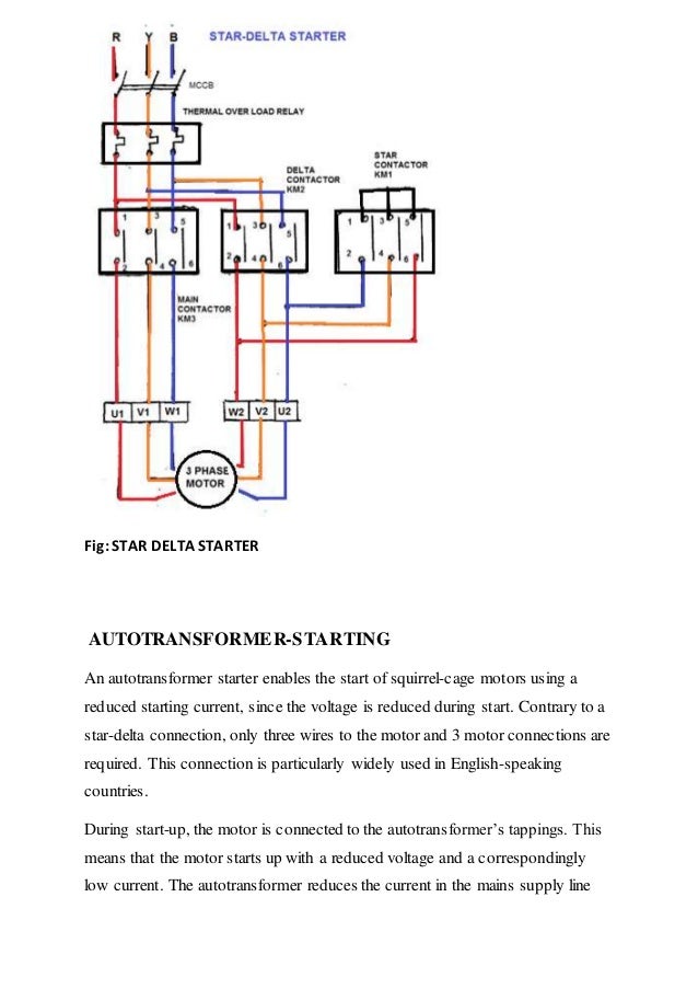
3 phase induction motor wiring diagram. Difference is that transformer is an alternating flux machine while induction motor is rotating flux machine. Dol starter is a simple starter used to start 3 phase induction motor. Thermal contacts tb white m 1 z2 yellow z1 blue u2 black u1 red bridge l1 and l2 if speed controller sc is not required m 1 ln e white brown blue l1 l2 n sc bridge l1 and l2 if speed controller sc is not required diagram dd9 1ø wiring diagrams ln e l1 l2 l3 sc z2 u2 z1 u1 cap. We can use dol starter where the starting current of motor will not affect the main power supply voltage. In this tutorial we will show the star delta y δ 3 phase induction ac motor starting method by automatic star delta starter with timer with schematic power control and wiring diagram as well as how star delta starter works and their applications with advantages and disadvantages. Dol starter capacity.
It is to be. Induction motor is a generalized transformer. Rotating flux is only possible when 3 phase voltage or poly phase which is 120 degree apart in time is applied to a three phase winding or poly phase winding 120 degree apart in space then a three phase rotating magnetic flux is produced whose magnitude is constant but direction keeps changing. There are three types of single phase induction motors which are the shaded pole split phased and capacitor motors. Shaded pole motor. Thus a capacitor start induction run motor produces a better rotating magnetic field than the split phase motors.
Diagram dd6 diagram dd7 m 1 ln e diagram dd8 ln e l1 l2 l3 sc z1 u2 z2 u1 cap. It is evident from the phasor diagram that the current through the starter winding is leads the voltage v by a small angle and the current through the main winding im lags the applied voltage. The heaviest load a shaded pole. It is important to point out from the phasor diagram that the phase difference between im and is is almost 80 degrees as against 30 degrees in a split phase induction motor. Capacitor motor single phase wiring diagrams always use wiring diagram supplied on motor nameplate. A three phase motor must be wired based on the diagram on the faceplate.
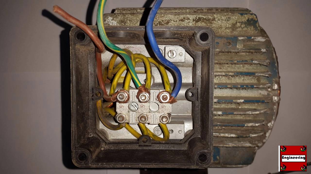
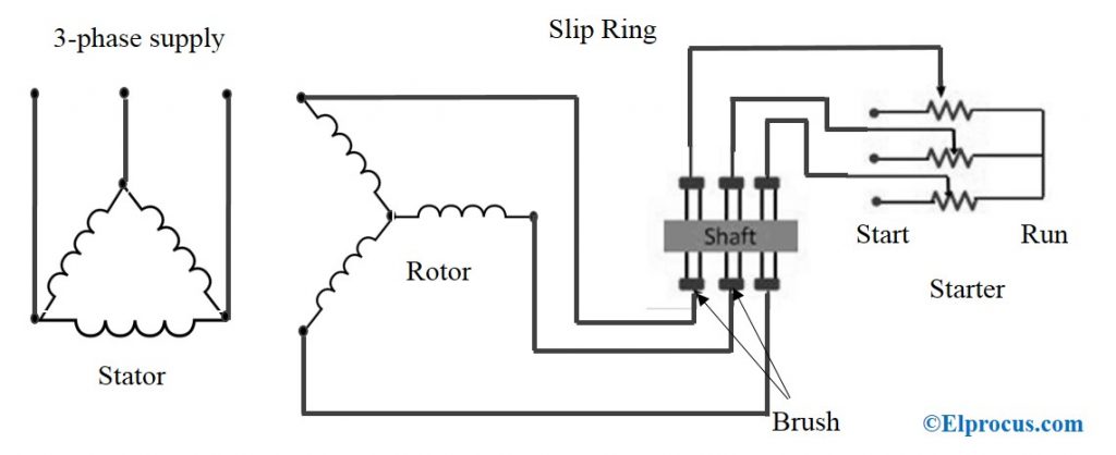
This video explains how to wire a three phase induction motor to an external electricity source. Shaded pole motors as seen in figure 3 are single phase induction motors found operating small cooling fans inside refrigerators in computers. Dol starter direct on line starter wiring diagram for 3 phase induction motor. In this starter 3 phase voltage directly applied to motor terminals without reducing the voltage by any method. It also shows the difference between delta and star connections used to connect the motor coils. What is dol starter.
That being said there is a wide range of different motors and what you have on hand can be completely different. They belong to the family of induction squirrel cage motors that are used in limited applications that require less than 34 horsepower usually ranging from 120 to 16 horsepower. Multi speed 3 phase motor 3 speeds 1 direction power control diagrams one line diagram of simple contactor circuit. For all other single phase wiring diagrams refer to the manufacturers data on the motor. The first step is to figure out the voltage of your phases. Thermal contacts tb white.
In the united states for low voltage motors below 600v you can expect either 230v or 460v.
Gallery of 3 Phase Induction Motor Wiring Diagram