If you buy 7x6 inch led headlights or 4x6 headlight and your car socket is not standard h4 to 3 pin adapter is a must. 3 bluetooth v21 edr class 2.

Loco Wiring Hand Control Amp Horn Relay Board 4qd Electric
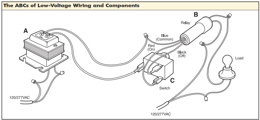
24v relay wiring diagram. 12 volt relay wiring diagram bosch relay wiring diagram 5 pole fresh 5 pin relay wiring diagram inspirational pin relay wiring. When the 24v is applied to the relay the relay just buzzes but contacts in the relay dont close to pass. Its fully insulated and contains up to 7. All low voltage components operate using 24 volts furnished by the step down transformer. As you can see there is absolutely no difference between the square type and the round type other than the ratings on the relay. When the 24v is applied to the relay the relay just buzzes but contacts in the relay dont close to pass through the 240v ac.
Relay logic provides you with a guide for using ncd relay controllers and how they can be wired for many types of applications. 7 external trigger input opto isolated switch low pulse inputs. Our relay logic guide. Provide the following with complete details. Use relay logic to control lights using relays in standard applications as well as 3 way switching application. A normally open relay will switch power on for a circuit when the coil is activated.
Confirm the operation by measuring the continuity at the line voltage terminations of each relay. Click on the image to enlarge and then save it to your computer by right. Assortment of 12 volt relay wiring diagram. Convert the given relay ladder diagram into plc system. The voltage should be measured at the field power connection point in the unit and while the unit is operating at full load maximum amperage operating condition. 5v 6v 9v 12v 24v dc motor.
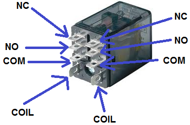
A normally closed relay will switch power off for a circuit when the coil is activated. Old low voltage wiring electrical systems use. The square relay pinout shows how the relay socket is configured for wiring. 5 pin relay 5 pin relays provide 2 pins 85 86 to control the coil and 3 pins 30 87 87a which switch power between two circuits. The main power from the battery feeding the fuse and relays should be a nice large gauge wire as indicated. Use relay logic to control the forward or reverse direction of motors.
The relay has a manual test button and if i press this everything works fine considerations when wiring low voltage control relays question. I am using 24vdc relays to switch 240vac 15ampon irrigation line. I am using 24vdc relays to switch 240vac 15ampon irrigation line. They have both normally open and. This pinout image is only a 2 pole diagram for room on the page purposes but you can get the picture here with this one since a 3 pole will just have 1 more set of contacts. Wiring diagram replaces 710890areplaces 710890a l2 l1 t2 t1 g n t4 l t2 t3 c t5 t1 y1 l1 l2 ecm y2 c 4 3 2 1 8 7 6 5 9 lrc y2 o w2 in w2 out df1 ambient ambg coilg coil demand defrost control board rev y valve hps lps y out y2 out c r s h c f reversing valve coil daul capacitor outdoor motor compressor trasformer 240v 24v high speed blower relay 24v blower relay blower motor com red black black brown blue compressor contactor black black yellow yellow yellow black yellow black see.
This caused the headlights not to work properly. Plc ladder diagram 24v r22 r3iri pbi 1 220 vac ri. This page demonstrates several simple ways to wire a relay for various applications. My 24v dc supply is only 1000 mamp. Headlight relay wiring diagram the above circuit is a way to use existing headlight wiring to control 2 relays that can be placed close to the lights. 10 relay maximum load10a250vac 10a125vac10a 30vdc 10a 28vdc 10a 12vdc.
Relay logic is all about wiring up relays for logical switching applications. Otherwise they work exactly the same. 11 ipb2 ri2 r32 r2 ll lif r13 m r21 r3 ipb3 r23 li. Low voltage relay wiring diagram. So use the right size wire.
Gallery of 24v Relay Wiring Diagram