Variety of 240v motor wiring diagram single phase. 240 vac motor wiring wiring diagrams hubs single phase motor wiring diagram with capacitor wiring diagram will come with numerous easy to follow wiring diagram directions.
3 Phase Drum Switch Wiring Diagram Ditinggalrabi 7
240 volt single phase motor wiring diagram. Wiring diagram images detail. Single phase motors are used to power everything from fans to shop tools to air conditioners. On the other hand this diagram is a simplified variant of this structure. Click on the image to enlarge and. It reveals the components of the circuit as simplified shapes as well as the power and also signal connections in between the tools. Single phase motor wiring diagram with capacitor baldor single phase motor wiring diagram with capacitor single phase fan motor wiring diagram with capacitor single phase motor connection diagram with capacitor every electrical arrangement is made up of various unique pieces.
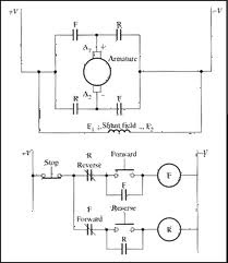
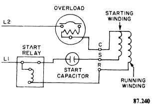
It is evident from the phasor diagram that the current through the starter winding is leads the voltage v by a small angle and the current through the main winding im lags the applied voltage. Each component ought to be placed and linked to different parts in particular manner. Single phase motor wiring diagram forward reverse single phase motor reverse and forward connection with capacitor wiring diagram. This makes the process of assembling circuit easier. 9 wire economizer plugs 3 amp fuse transformer high pressure switch low pressure switch black reversing valve solenoid orange blue 24v 208v com 240v black 7106191 convertible packaged heat pump 208230 volt single phase 60hz. Disconnect all power before servicing.
Wiring a motor for 230 volts is the same as wiring for 220 or 240 volts. Motor accessory heat plug c r s r c s l2 l1 t2 t1 terminal strip economizer jumper harness assy. Residential power is usually in the form of 110 to 120 volts or 220 to 240 volts. Higginbotham wiring diagram wiring diagram ac sharp 240 volt single phase wiring diagram 240v single phase motor wires required single phase 240v transformer wiring diagram single phase ac wiring diagram 208 volt single phase. Assortment of single phase motor wiring diagram forward reverse. December 13 2018 april 12 2020 wiring diagram by anna r.
It is important to point out from the phasor diagram that the phase difference between im and is is almost 80 degrees as against 30 degrees in a split phase induction motor. 240 volt switch wiring diagram wiring diagrams hubs 240 volt single phase wiring diagram the diagram provides visual representation of the electric arrangement. For supply connections use copper conductors only. For all other single phase wiring diagrams refer to the manufacturers data on the motor diagram dd6 diagram dd7 m 1 ln e diagram dd8 ln e l1 l2 l3 sc z1 u2 z2 u1 cap thermal contacts tb some standard frame induction motor diagrams have been included for ease of presentation pgs ocdedv gamma series d 1417 diags er 1 2 4 5 ocd magnetic starter 30a 120240v coils this magnetic starter is a 3 phase full voltage across the line starter with the coil factory wired for 208 240 volts. It is intended to help all the typical user in building a correct program. If not the arrangement wont work as it should be.
These instructions will probably be easy to comprehend and implement. Some motors allow both 120 volt and 240 volt wiring by providing a combination of wires for doing. 240 volt single phase wiring. Not suitable on systems that exceed 150v to. A wiring diagram is a streamlined conventional pictorial depiction of an electric circuit. It is to be.
Thus a capacitor start induction run motor produces a better rotating magnetic field than the split phase motors. 240 volt single phase wiring diagram. 240 volt single phase wiring will definitely help you in increasing the efficiency of your work.
Gallery of 240 Volt Single Phase Motor Wiring Diagram