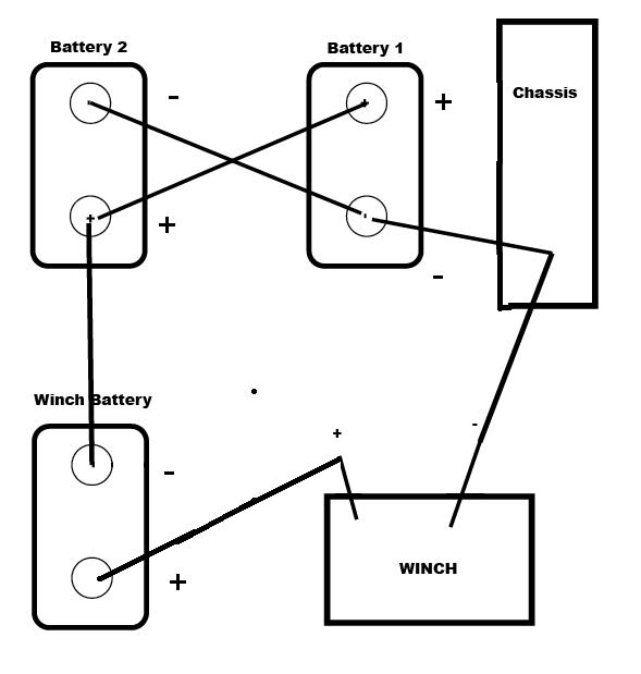
Depending on how theyre wired two 12 volt batteries yield a 12 volt system with double the amps or a more efficient 24 volt system with twice the cranking speed there will be 12 volts about 142 volts with an alternator if the batteries arent wired together but kept isolated. Trolling motor wiring diagrams.
6 Volt Charging System Wiring Diagram H1 Wiring Diagram
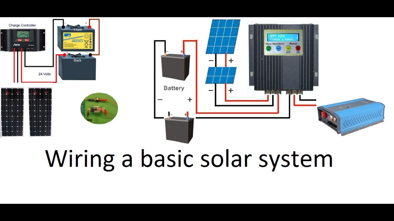
24 volt system wiring. Parallel wiring two panel solar system. The wire sizing guide below provides the minimum wire size needed to limit voltage drops to 5 at a given distance in a 12v or 24v system. Wire in series only as directed in wiring diagram to provide 24 volts. These larger motors and multiple batteries are wired in a series pattern and optimally the circuit breaker should be wired within 4 of your battery. The reduction in wire size cuts down the costs as the thicker the wire the more costly it is. Fine but wasnt wired to our diagram below.
Plug in the new trolling motor into the original trolling motor receptacle. While small and medium trolling motors use a single 12v marine battery larger trolling motors use larger 24v and 36v systems and require 2 or 3 marine batteries accordingly. For a 48v system multiply the distance taken from the 24v chart by 2. If you want to limit your losses to 2 simply divide the distance by 25. Volts with two solar panels and two batteries wired in series your panels volts increase to 36 volts and your battery banks volts go to 24 volts which means youll be able to power up to 24 volt appliances. Two 12 volt deep cycle batteries are required.
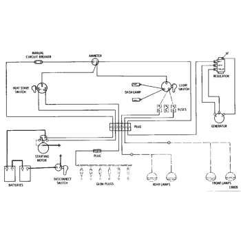
24 volt systems 2 batteries. Lets calculate the wire size for the same pump in the same boat but this time lets assume that the boat has a 24 volt system. That means that the same 240 watt bilge pump will draw only 10 amps 240 24 and that a 10 percent allowable voltage drop will be 24 volts 24 v x 010. We re wired the system to the return circuit is carried back to the battery by wires instead of through the in the middle of the series deere returned to hooking the batteries in. Make sure that the trolling motor is switched to the off position or speed selector set to 0. Attach the black wire from the original system to the negative post of the added battery.
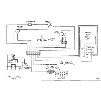
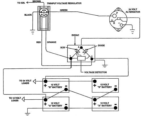
There will be 12. The samlex charger can fully recharge my 150 ah batteries at 50 discharge in just over four hours. Promariner makes marine chargers in all sizes and all configurations. John deere 24 volt electrical systems on electric start 70 and diesels. Wiring a 24 volt charger into your system is easier to do and requires two fewer connections. Remove the 12 volt trolling motor from the boat and mount the new 24 volt trolling motor.
This is so because increasing the voltage of a system causes a reduction in the current through it and in turn reduces the size of the wires you need. Using a 24 volt supply instead of a 12 volt supply greatly reduces the wiring cost to almost half the original cost.
Gallery of 24 Volt System Wiring