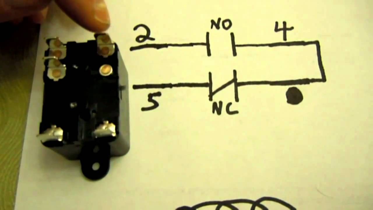
Mks2pidc mks2pi dc b. If any students ask what spdt means refer.
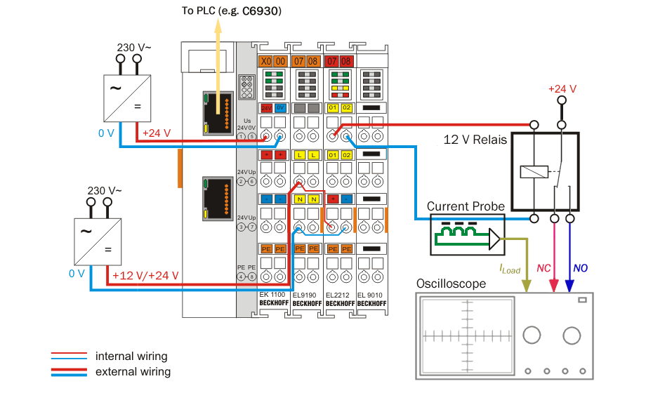
Beckhoff Information System English
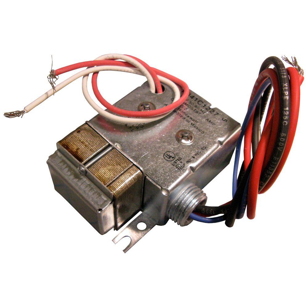
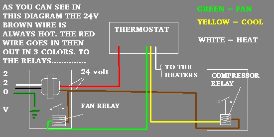
24 volt relay diagram. Honeywell fan relays wiring diagrams. Thermostat relay wiring wiring diagram honeywell fan center honeywell furnace relay fan center relay wiring diagram honeywell chronotherm iii wiring diagram honeywell switching relay 5 post relay wiring diagram hvac control board wiring diagram 2pelzmoden muellerde. The purpose of a relay is to automate this power to switch electrical circuits on and off at particular times. S13 ignition switch wiring diagram. John deere 24 volt electrical systems on electric start 70 and diesels. Well call this mtr1motor1.
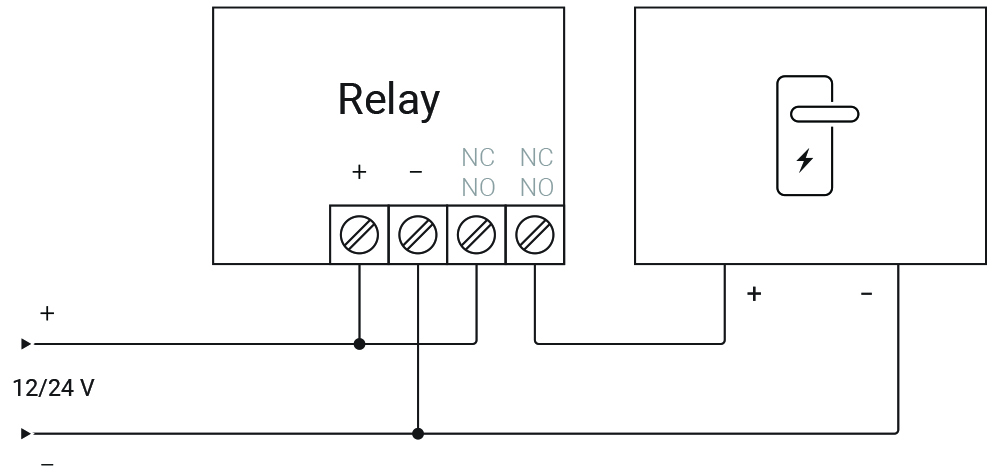
12 24 24 yes. If the wiring of your direct current relay the procedure you would undertake would include a 24 volt direct current negative which is the signal ground and a 24 volt direct current negative. It reveals the parts of the circuit as streamlined forms and the power as well as signal links between the devices. 2005 peterbilt 379 wiring diagram. For the next step you have to include the relay arm and then the relay will normally close. 24 volt battery wiring diagram.
A motor starter is just another name for a certain type of relay that is used to control a motor. Modified power wheels. It really is meant to assist all the common person in creating a correct system. 24 3pdt 3 pole no. Built in ω. In a 24 volt dc direct current relay the twenty four volt direct current is classed as the input and the relay is the output.
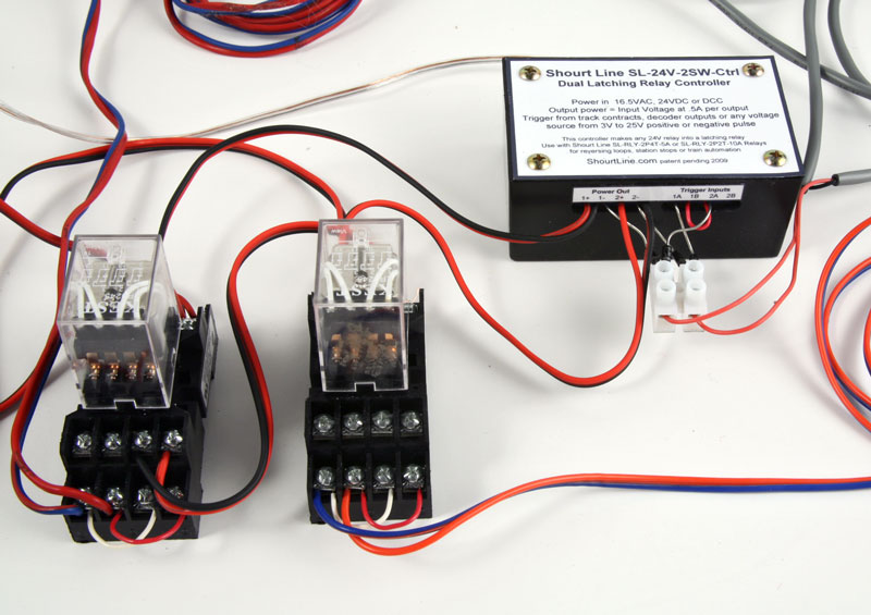
John deere starter relay wiring diagrams. 1 pcs relay omron mks2pi 24vdc socket 2 pcs accu 12 volt serie up 24v dc sesuaikan tdr berikut gambar rangkaian utama dan wiring diagramnya. Wiring diagram comes with a number of easy to follow wiring diagram guidelines. The real benefit behind a relay is more than automation. These directions will be easy to understand and implement. Then you have connect the photo sensor negative black to the photo sensor.
Wiring diagram sheets detail. 12 volt relay wiring. Now these diagrams are known as relay logic or ladder diagrams. With this guide you may be able to. Now in the diagram below i have added a motor starter. Spdt relay wiring diagram wiring diagrams click 12 volt relay wiring diagram.
The tm i have covers only pre side console the parts counter at your jd dealer should be able to print that diagram from their parts. 12 volt relay wiring diagram bosch relay wiring diagram 5 pole fresh 5 pin relay wiring diagram inspirational pin relay wiring. Octal base general purpose relays. Its using relays to control the circuit and also the diagram will begin to take the shape of a ladder as the relay logic grows. Two power sources one. John deere 12 volt wiring diagram including john deere 24 volt system together with john deere starter relay including wiring diagram john.
24 volt relay diagram. Assortment of 12 volt relay wiring diagram. The logic here is the same as. 5x 12 volt 3040a spdt relay wire. Car qook automotive dc 12v 12 volt 30a amp spdt wiring power relay. Long life minimum electrical operations.
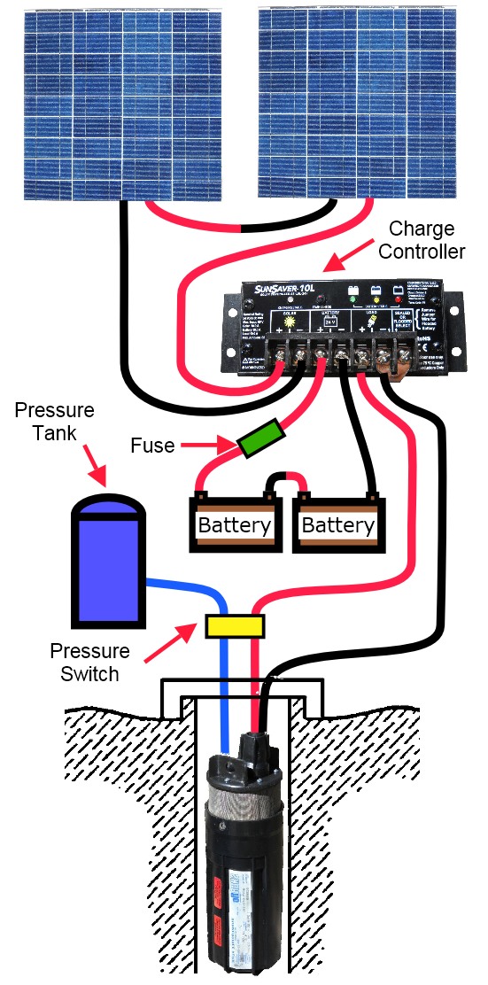
It will continue downward as you will see later on. Variety of 12 volt solenoid wiring diagram. The switch only controls the relay. How to operate relay omron mk2p 220vac. 24 volt battery diagram wiring diagram and schematics how to configure a battery bank 12 volt battery wiring layout 4 battery 24 volt wiring diagram pdf imageresizertool 4 battery 24 volt wiring diagram pdf to her with wiring diagram ford 3000 sel tractor also more build solar voltage regulator along with disconnect. There you have it.
3 pos switch wiring diagram tractor parts repair and images john deere wiring schematic wordpress. Complete the schematic diagram for a spdt relay circuit that energizes the green light bulb only when the pushbutton switch is pressed and energizes the red light bulb only when the pushbutton switch is released. Click on the image to enlarge and then save it. 12 volt relay wiring schematic. In order for this circuit to function as specified the green light bulb must receive power through the relays normally open contact and the red light bulb through the relays normally closed contact.
Gallery of 24 Volt Relay Diagram


%2C445%2C291%2C400%2C400%2Carial%2C12%2C4%2C0%2C0%2C5_SCLZZZZZZZ_.jpg)