If pump shutdown is desired for a leakage situation connect minicas contacts 1 3 11 8 in series. Flygt offers minicas relays in two interchangeable variants.
Flygt P7030 P7035 P7040
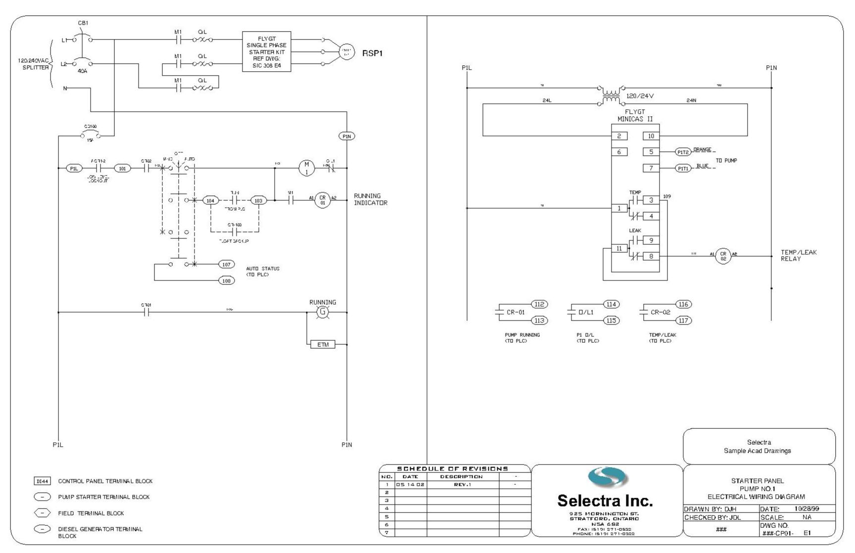
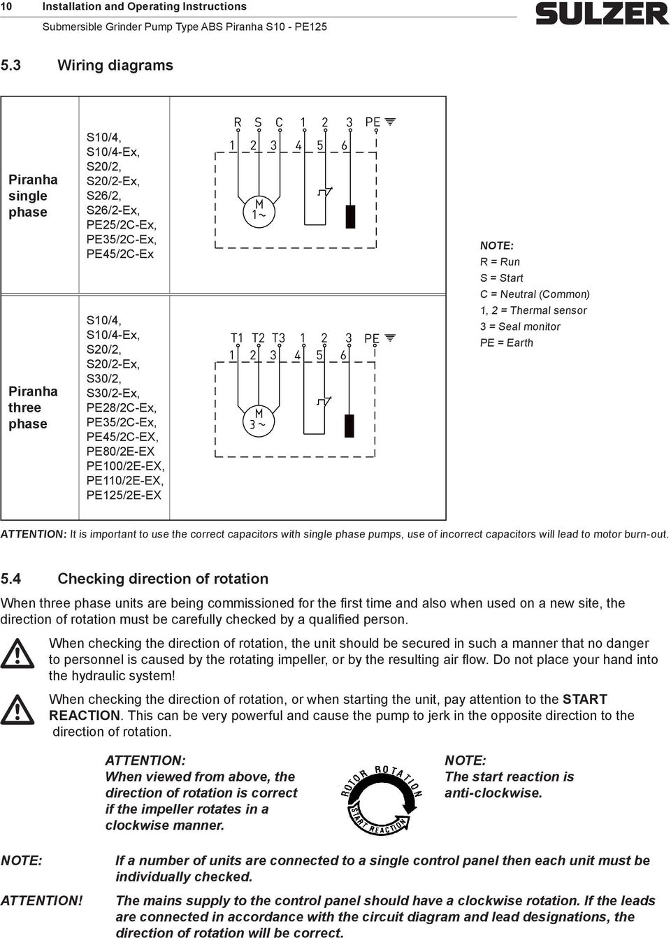
Flygt control panel wiring diagram. 11 8 closed 11 9 open. Unit operates on 24 vac 24 vdc or 120 vac supply. Sump pump control panel wiring diagram wiring diagram is a simplified all right pictorial representation of an electrical circuit. Overtemperature relay contacts. Communication port 37 38 for rs 485 is common to both pump memory and operator panel. Not only a contactor but also i install the thermal overload relay which will protect the motor form burning in case of over current flow to the circuit.
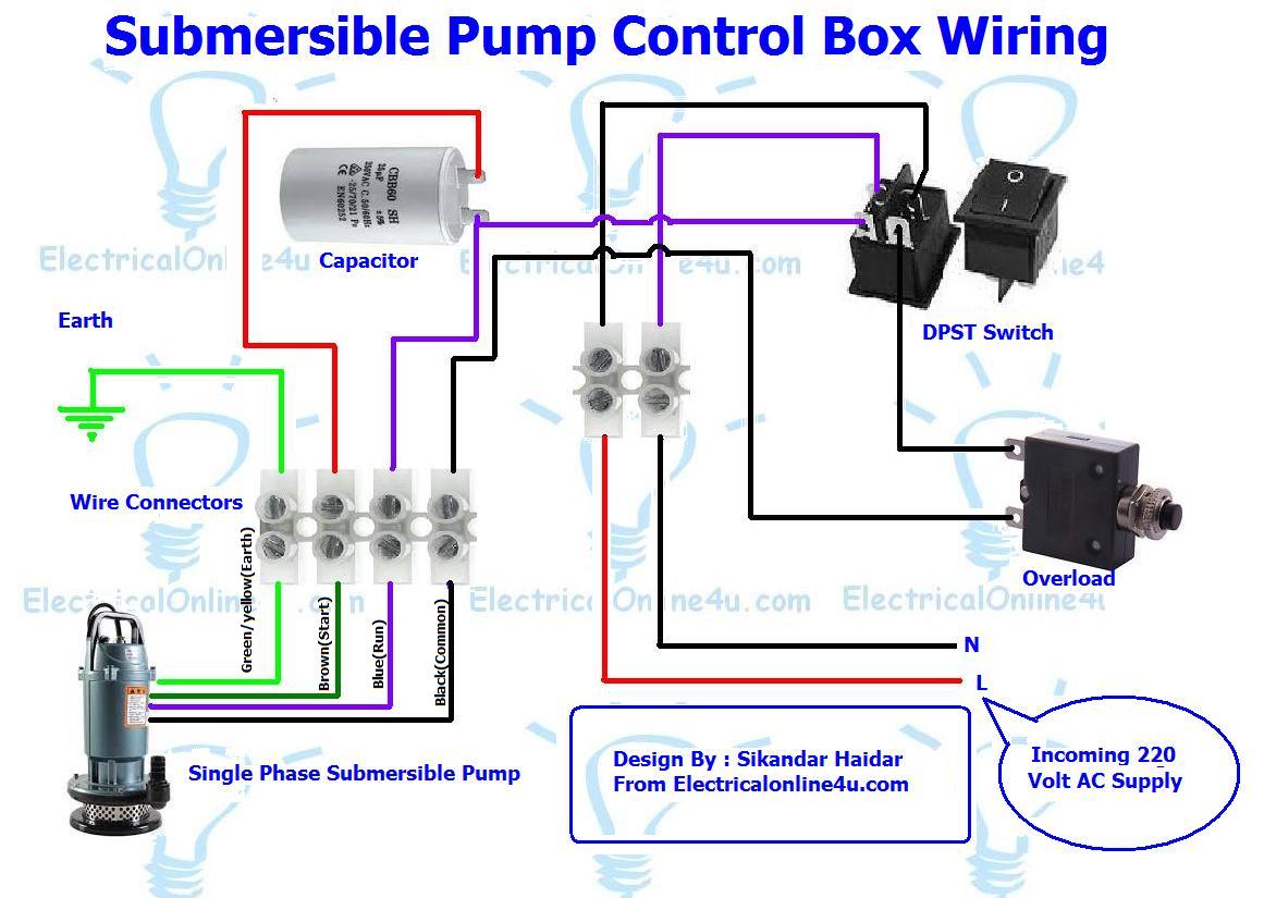
In auto mode the pump will start using a standard. If an overtemperature condition occurs the. Wiring diagram minicasfus see note 2 notes. 1 3 closed 1 4 open. Lets start with the most basic float switch. The wiring connection of submersible pump control box is very simple.
In this video we will look at the control wiring for a 3 phase pump panel and how a pump is controlled both in auto mode as well as hand mode. It shows the components of the circuit as simplified shapes and the aptitude and signal connections amid the devices. Wiring diagram minicas llfus 120 mode of operation. In which i control a three phase submersible pump motor using magnetic contactor. In the diagram i showed the 3 pole mccb breaker magnetic contactor thermal overload protection relay and normally open normally close push button switches. Dc power supply required for 24 vdc applications.
Terminal this is a wiring diagram of the sensor terminals section 2 used for a subcab 24 lead diagram sensor cable. Wiring diagram minicas llfus 120. Keep me on the current site. Mas 711 measuring instruments pdf manual download. Control transformer required only for 24 vac applications. 24 vac24 vdc ac neutral 1113 612 operation the minicas provides motor over temperature and seal leakage protection for flygt submersible pumps equipped with fls or cls.
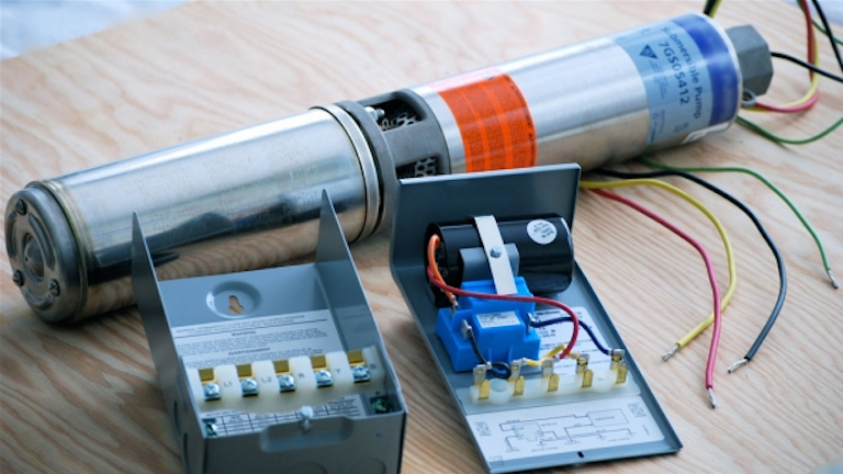
It looks like you are coming from united states but the current site you have selected to visit is united kingdomdo you want to change sites. A two wire single pole single throw float switchthe rising action of the float can either close ie turn on a normally open circuit or it can open turn off a normally closed circuitinstallation scenarios might include a normally open float switch turning on a pump to empty a tank control schematic 2 or a normally closed float switch turning off a pump that fills a tank control schematic 1. Single phase submersible pump control box wiring diagram 3 wire submersible pump wiring diagram in submersible pump control box we use a capacitor a resit able thermal overload and dpst switch double pole single throw. It looks like you are coming from united states but the current site you have selected to visit is canadado you want to change sites. Keep me on the current site. 3 phase submersible.
Wiring midrange pumps subcab 12 lead sensor cable alternative 1 installation wiring midrange pumps subcab 12lead sen sor cable. Leakage relay contacts. Today i am here to share with you the 3 phase submersible pump wiring diagram. View and download flygt mas 711 installation and operation manual online. In normal conditions when the minicas 120 is powered the green led is on and the relay contact status is as follows. Minicas ii with external manual reset after an.
Here is the complete guide step by step.
Gallery of Flygt Control Panel Wiring Diagram