Electrician circuit drawings and wiring. The wattmeter is an instrument for measuring the electric power in watts of any given circuit.
Types Of Electrical Diagrams
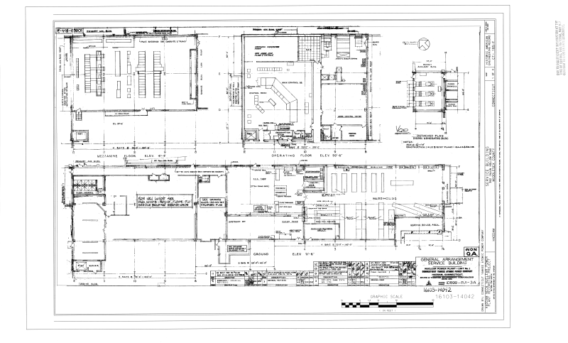
Examples of electrical drawings. Basic electrical diagram electrical wiring diagram circuit control diagram more related articles electrical diagram. When an electrical drawings is performed. Basic electrical design of a plc panel wiring diagrams on photo. Modern industrial automation panel. These dimensions have been taken from din and its use has been generalized worldwide the following figure shows a scheme where you can see the different formats. Magnet core ferrite core igniter plug bell.
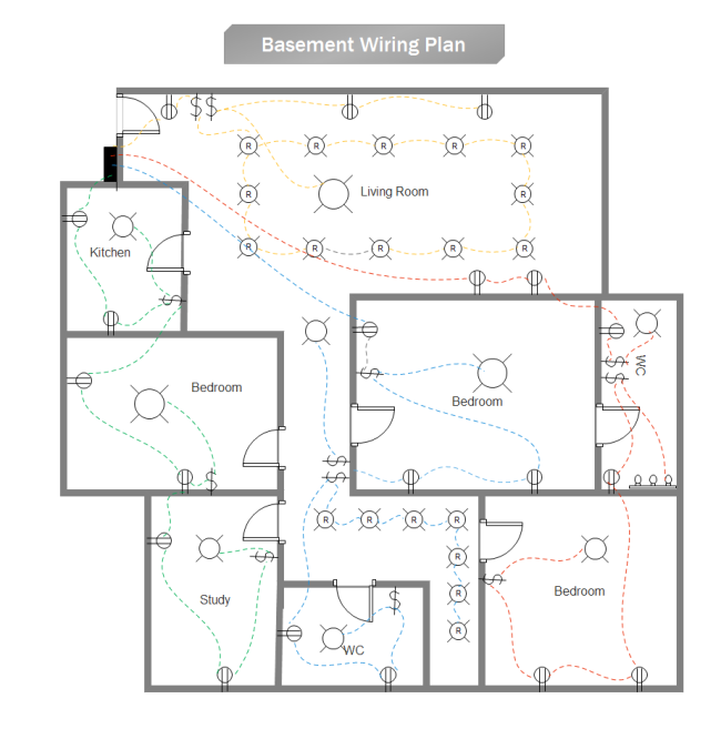
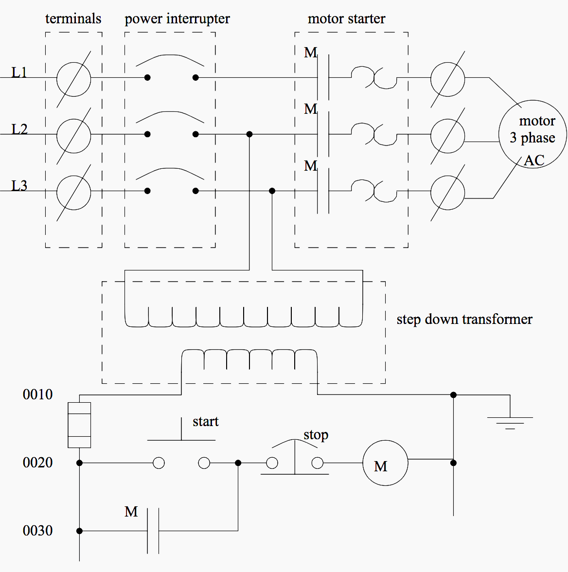
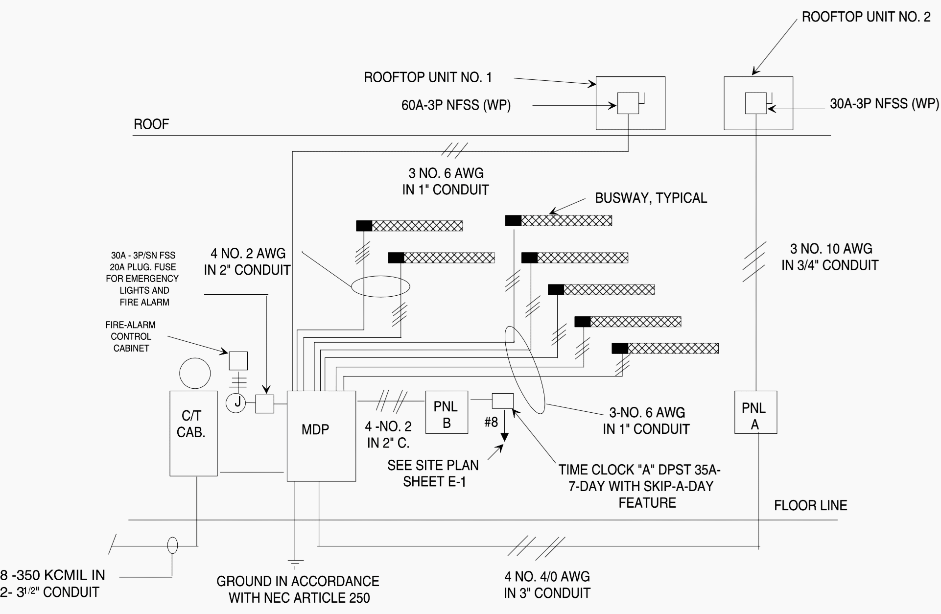
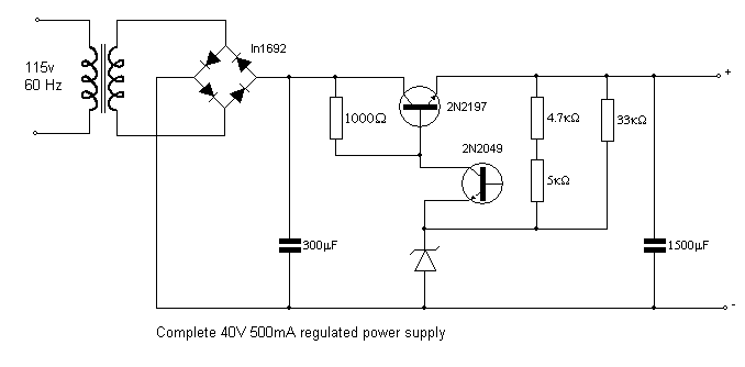
Electrical drawings plays an important role in electrical installation works that they convey information about connection of various devices and equipments with mains. A more complex example the electrical circuit of an automobile is shown in wiring diagram format in figure 11 and in schematic format in figure 12. Electrical drawings are technical documents that depict and notate designs for electrical systems. Browse electrical plan templates and examples you can make with smartdraw. Before knowing about these diagrams first one must aware and have idea about various symbols used while preparing drawing. The following table shows the formats used for drawings the dimensions of each of the formats and margins must have.
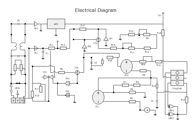
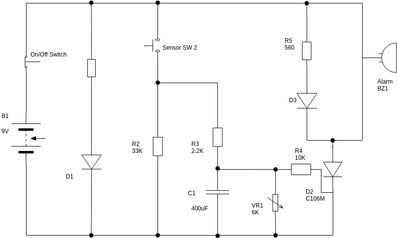
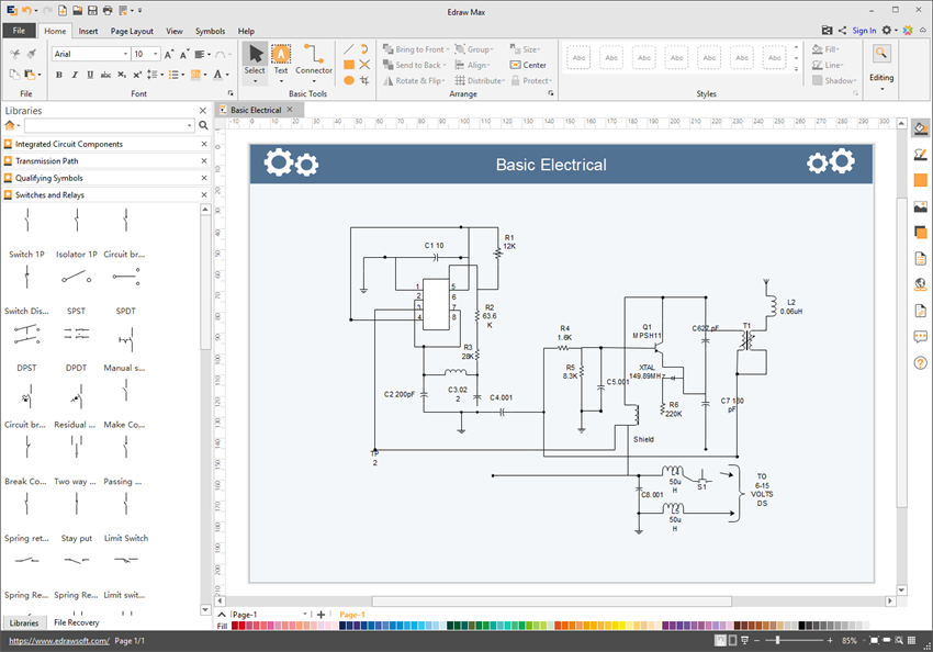
Electrical drawing example using these above electrical symbols can help you draw standard electrical diagrams. The circuit could be more complicated if the student understands the concepts. The best way to understand wiring diagrams is to look at some examples of wiring diagrams. One of the aspects to be taken into account is the size of paper used. Permanent magnet a permanent magnet is a material or object that produces a magnetic field. For example once the electrical designs are complete they must be built by an electrician.
The information on drawings provides the complete design or plan of electrical installation and also helps to assemble the various equipments. Some of the electrical wiring diagrams are discussed below. This article discusses the design issues in implementation that must b. For example a voltmeter is an instrument used for measuring the electrical potential difference between two points in an electric circuit. Generally the drawing is set to the most comfortable size for the end user. Workers use these documents to install systems on site.
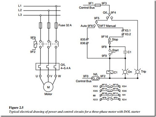
Wiring from a switch box running two lights. Adding the components names on each symbol makes it easier for both beginners and professionals to understand the circuits in seconds. Click on any of these wiring diagrams included in smartdraw and edit them. Material delay element the delay element provides a specified delay between the actuation of the propellant actuated devices. How to read electrical drawings learn the symbols used to notate components in an electrical drawing. Notice that the wiring diagram figure 11 uses both pictorial representations and schematic symbols.
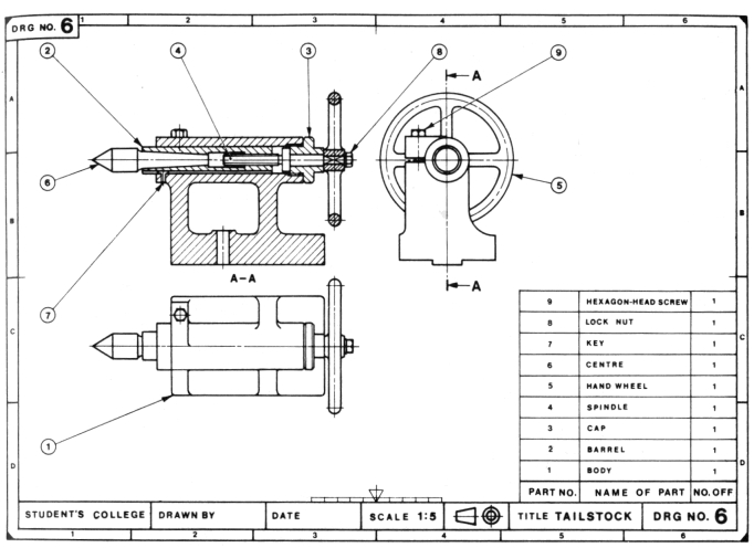
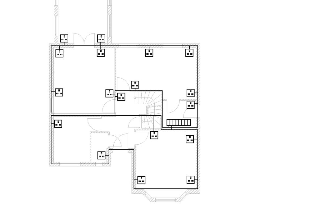
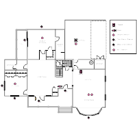
Lights use autocad tools to diagram lighting sources from klieg lights to sconces. Understands basic types of electrical drawings can produce a floor plan that displays understanding knows the difference between a circuit drawing and a wiring diagram draws and understands a wiring diagram extension activity draw more wiring diagrams that include more devices in different configurations. Therefore it is your responsibility to effectively communicate your design intentions to the electricians through drawings. Here are some good looking electrical drawing examples and you will find more in edraw template center. In electrical drawings every type of component and connection has its own specialized symboland every detail matters.
Gallery of Examples Of Electrical Drawings